Tell us moreHow about a schematic?

What else would you like to know? I don't mind sharing. But I'm at work right now
and don't have access to my schematic.

It should also be noted that for me, aside from the BA PCB, this is a point to point wired,
ongoing experiment/hobby/fun thing to do. I use the BA OPS as a platform for
experimentation with different input, VAS, and buffer designs, and I am not done with
that experimentation. But what I have has impressive me enough to pause development
and re-listen to my music collection.
I will need to update my schematic to reflect the current state of the design and maybe
run some new performance tests. When I get that done, if you're interested, I could post
it under a new thread (I think this is drifting away from the original intent of this thread).
Similarly, back in the magma thread, Nelson suggested that we play around with
different transformers. I have done a little of that. Maybe we need to design a
standardized way of testing transformers and create a new thread (data repository) for
that?
Thanks,
Robert
I've tried the F4 with the ACP+ as well. The gain was a bit on the low side
but it sounded great anyway.
Adding the BA3 preamp will give you essentially the BA3 push-pull amp.
It will be great.
Cheers,
Dennis
I agree. The ACP+ sounded great but the gain was lower compared to the H2 preamp. Not that I need a whole lot of volume these days...
BA3 preamp is next.
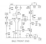
BA2 is virtually the same thing.
Yep! wanted to edit my post, but was to lazy
Felt like pointing it out. A lot of people have forgotten or overlooked that BA2 is actually a very nice circuit.
There are a couple of tweaks that can be implemented, to make it even better.
That part I do not know.
care to elaborate (apart from building ZM's  )?
)?1) Make R207 ZERO
2a) Reduce R208/R209 to 500 Ohms
2b) Increase Bias of Q2 to between 22mA and 24mA
3a) Make R205 ZERO
3b) Make Q202 - 2 or 3 N-Channel Jfets (in parallel) as constant current sources to achieve total of 10mA
4a) Make R210/R211 10 Ohms
4b) Make C205/C206 4700uF
3a) and 3b) may not be super important, I am a little OCD about certain things.
The other mods should definitely be implemented.
Attachments
Last edited:
1) Make R207 ZERO
2a) Reduce R208/R209 to 500 Ohms
2b) Increase Bias of Q2 to between 22mA and 24mA
3a) Make R205 ZERO
3b) Make Q202 - 2 or 3 N-Channel Jfets (in parallel) as constant current sources to achieve total of 10mA
4a) Make R210/R211 10 Ohms
4b) Make C205/C206 4700uF
3a) and 3b) may not be super important, I am a little OCD about certain things.
The other mods should definitely be implemented.


What else would you like to know? I don't mind sharing. But I'm at work right now
and don't have access to my schematic.
It should also be noted that for me, aside from the BA PCB, this is a point to point wired,
ongoing experiment/hobby/fun thing to do. I use the BA OPS as a platform for
experimentation with different input, VAS, and buffer designs, and I am not done with
that experimentation. But what I have has impressive me enough to pause development
and re-listen to my music collection.
I will need to update my schematic to reflect the current state of the design and maybe
run some new performance tests. When I get that done, if you're interested, I could post
it under a new thread (I think this is drifting away from the original intent of this thread).
Similarly, back in the magma thread, Nelson suggested that we play around with
different transformers. I have done a little of that. Maybe we need to design a
standardized way of testing transformers and create a new thread (data repository) for
that?
Thanks,
Robert
It wouldn't fit in 6L6s build guide thread, but I think is totally fine/appropriate for this one. In my mind this thread is about what you can do to improve/change the basic f4 circuit at this point in its life span. Anyone interested in the basics or needing stock build tips will be over in the wonderful guide thread.
It is worth pointing out also, that if you were going to use this as preamp for F4 then also completely delete C208/Out connection.
What else would you like to know? I don't mind sharing. But I'm at work right now
and don't have access to my schematic.
It should also be noted that for me, aside from the BA PCB, this is a point to point wired,
ongoing experiment/hobby/fun thing to do. I use the BA OPS as a platform for
experimentation with different input, VAS, and buffer designs, and I am not done with
that experimentation. But what I have has impressive me enough to pause development
and re-listen to my music collection.
I will need to update my schematic to reflect the current state of the design and maybe
run some new performance tests. When I get that done, if you're interested, I could post
it under a new thread (I think this is drifting away from the original intent of this thread).
Similarly, back in the magma thread, Nelson suggested that we play around with
different transformers. I have done a little of that. Maybe we need to design a
standardized way of testing transformers and create a new thread (data repository) for
that?
Thanks,
Robert
Some pictures would also be nice. I'd love to see an example of an f4 with pTp wiring. I think these are my final amps, so I like to entertain any option that people argue increases perceived sound quality.
'also completely delete C208/Out connection'
And replace R208 & R209 with a CCS.
Might be a headache implementing that on the existing board though.
Resistive loads are absolute fine for low power applications.
I just finished building mine and something is wrong. It sounds a little harsh with glare. I have an M2 for comparison, so I can tell quite easily that this has more distortion. Tonight, I will hook it up to a dummy 8R load and a voltage divider to measure distortion and look at the profile of different HD components, but wanted to see if there are other things to check first.
Some details about the build:
- IRFP240 and 9140 pairs, match to 0.02V Vgs (yes, 0.02, not 0.2).
- BL grade JFETs, matched at Idss 10.3 mA.
- Biased at about 220 mV.
- DC offset <10 mV
- Biasing and DC offset worked right off the bat. In fact, I encountered no other problems at all, which is surprising
- Source is RME ADI-2 Pro. I tried a couple of gain settings and they both sounded the same. The glare/distortion is not there with the M2.
- Found that I can get enough volume with just the RME, though I'll be adding another preamp between the RME and F4 later. It gets plenty loud and there is enough power here.
- Checked dc offset during operation after an hour, it was still quite low.
Might be a headache implementing that on the existing board though.
Resistive loads are absolute fine for low power applications.
Nah, 3d it, build the CCS on a small piece of vero and mount vertically on the resistor pads
Just call me BBB, bloody bastard brother
Last edited:
It wouldn't fit in 6L6s build guide thread, but I think is totally fine/appropriate for this one. In my mind this thread is about what you can do to improve/change the basic f4 circuit at this point in its life span. Anyone interested in the basics or needing stock build tips will be over in the wonderful guide thread.
Well, if there is a problem, let me know and we can move this elsewhere.
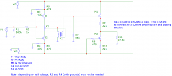
Here is a schematic of the input buffer, voltage amplification section, and
the following buffer. This is from my memory and notes I have here at
work, but I think it is correct.
The exception to that is R7. R7 is used for transformer frequency response
compensation (filter the ringing). R7 is a theoretical and is a goal. In my
working circuit, this is actually an RC circuit, but I don't remember the values.
I also have a 475 ohm resistor on the gate of M1, but again, I think the
inductance of the transformer with R7 should relieve that need. But this is
and area that shows the difference between theory and practice. (or maybe
I'm a perfectionist).
Remove R11 and the associated ground, and connect to your output section.
My OPS is capacitor coupled and therefore needs the current supplied by the
second buffer. At 33V rails, the second buffer is biased to about 10mA. I
use heat sink caps on the DN2530's as they are near their power limit.
I should be able to post some pictures later.
Thanks,
Robert
Attachments
Have you measured dc voltage drop across every source resistor?
Also check noise at output.
I think my amp had something like 0.005% distortion possibly better.
Thanks! I haven’t checked each source resistor. Will do that. Is that distortion figure at 1 W output? My plan was to check at 1 W into 8R.
Point to point wiring for the entire circuit? That would be an interesting challenge. Might look interesting if done with an artistic eye.
Not sure if I’d be willing to have the extra parasitics and increased RF susceptibility though...
Don't expect anything artistic from me!
I have no kids or pets,so I can keep the amp pretty open and accessible (as you will see
when I post pics). You're quite right about the rest. That is something
to keep in mind when looking at the performance graphs.
Dividing the circuit into sections helps with experimentation and
making the PtP wiring feasible. The buffers are simple to make and
easily switched to a different design (which I took as the main point
of the BA project.)
Thanks! I haven’t checked each source resistor. Will do that. Is that distortion figure at 1 W output? My plan was to check at 1 W into 8R.
Yeah 1 W into 8 Ohms.
- Home
- Amplifiers
- Pass Labs
- F4 power amplifier