Has anyone out there used the Store Deluxe Store 4U chassis for an F4?
Yes - the location of the devices on the heatsink is absolutely no problem whatsoever. I can run the F4 at higher bias than suggested in the F4 manual.
if the goal is to have minimum even harmonics at the speaker,would it make sense to use a line level splitter like attatched, with low even harmonics numbers, and then feed it to a complete symetric path to the speaker(for example, balanced bride of zen+circlotron follower) ?
as opposed to say, feed a line level signal to a scaled down son of zen with one input grounded,or an opamp-splitter (like juma did), to generate a balanced signal?
Great drawing pidesd !

")
There's a far better way to exploit that idea - see Chris Hornbeck's proposal (post #148):
http://www.diyaudio.com/forums/tubes-valves/189153-phase-splitter-issue-3.html#post2802454
For one of possible practical renditions of that circuit see attachment. CCSs (Q5,Q6) should be matched to provide the same current (15mA) by means of R5,R15. P1 sets the DC offset.
Attachments
Juma,
At first glance, I would think that outputs would not be symmetrical, with the negativee half having a greater amplificationfactor. Not arguing, just don't really understand.
The positive half would appear to have no gain, coming out of the source pins of the FE.
At first glance, I would think that outputs would not be symmetrical, with the negativee half having a greater amplificationfactor. Not arguing, just don't really understand.
The positive half would appear to have no gain, coming out of the source pins of the FE.
Last edited:
Buzz, let me help you understand: there are no halves, it's the same circuit as in LSKpre thread. If you omit all the spectacular stuff (complementary pair, folded cascodes, biasing, etc...) essentially you'll have a JFET with Rs=Rd ie. R6=R9 (condition for A=1) and one output taken from the source and the other from the drain, just like the simple cathodyne phase splitter.
It's true that outputs won't be absolutely equal but the other way around (negative phase will be 2-3mV lower) due to the fact that Rs includes internal resistance of JFET but it's easy to adjust it by adding a few Ohms to the value of R9.
Also, the Zout of both outputs won't be absolutely equal but with the load that is high enough (10k or more) it won't matter.
Last edited:
Maybe +OUT can be the input signal +IN instead of that indicated [cleaner], and then tweak -OUT by measurement to make it equal in amplitude.Well explained, as usual. Thanks.
Great drawing pidesd !
There's a far better way to exploit that idea - see Chris Hornbeck's proposal (post #148):
http://www.diyaudio.com/forums/tubes-valves/189153-phase-splitter-issue-3.html#post2802454
For one of possible practical renditions of that circuit see attachment. CCSs (Q5,Q6) should be matched to provide the same current (15mA) by means of R5,R15. P1 sets the DC offset.
Hi Juma,
Is this circuit being suggested as appropriate for adding a pot on the +/- outs to make it a "pre" for a balanced F4, or is it being considered as a *replacement* of a balanced F4 front end so that it can be driven by a single ended unity gain buffer preamp?
Big E,
i m not sure 100% of what you mean, but the phase splitter posted by juma is a unity gain buffer.
Actually it gives close to 6dB gain - for 1V SE input you'll get about 2V balanced (~1V per phase).
Finally...Pics of the Fugliest F4 in the world!
Ok, Fugliest in the world in my opinion!
I know my power supply approach is probably a bit unorthodox, but I ruined my PD boards with a stupid mistake. I was going to buy more, but this worked and the amp is dead quiet and sounds great. My 845 amp is driving the F4, which is providing power to the MTM portion of my VSA VR-35s. It sounds wonderful at normal levels at which I listen (75-85 db). However, when I crank it, I am quick to understand that my next project will be a higher wattage amp! The pics are not that great, but you'll get the idea: I am a novice with zero chassis building talent. Thanks for all your help (even though you didn't know you were giving it to me!)
https://picasaweb.google.com/117221555538051805236/DIYF4Amplifier?authuser=0&authkey=Gv1sRgCM7q4svVubmt3QE&feat=directlink
Last edited:

for all your help (even though you didn't know you were giving it to me!)
Next time turn your heatsinks around

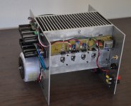
Maybe it is all right the way you have it; provided the suggested heatsink temperature is not exceeded. As you have it, heatsink temperature is probably uniform through out versus some gradient with the alternate fins perpendicular to the chassis; because cool air enters at the bottom, rushes upward across the fins and emerges as a hot wind at the top. Fortunately, as you listen to your diyF4 you will be doing the experiment.Fins to the Left, Fins to the Right, You're the Fugliest Amp in Town!
Yes, I knew you folks would pick up on that mistake right away. It adds a certain je ne sais quoi don't you think?
Last edited:
- Home
- Amplifiers
- Pass Labs
- F4 power amplifier