question about "biamplied" F4
Dear Mr. Pass, et al,
I am about to ask a stupid question, here goes...
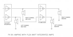
I have noted that when driving the F4 from a tube amp, you have suggested to add an appropriately sized resistor to load the tube amp. However, when using the "biamplied" method where treble portion (actually the MTM) of the speaker is connected to the tube amp's speaker terminals and the bass to the F4, the resistor should be removed, correct?
Thank you all in advance (please commence making fun at my expense ),
),
Gary
Dear Mr. Pass, et al,
I am about to ask a stupid question, here goes...
I have noted that when driving the F4 from a tube amp, you have suggested to add an appropriately sized resistor to load the tube amp. However, when using the "biamplied" method where treble portion (actually the MTM) of the speaker is connected to the tube amp's speaker terminals and the bass to the F4, the resistor should be removed, correct?
Thank you all in advance (please commence making fun at my expense
),Gary
Output Transformer behave differently with different loads. If you drive only the f4 it at 47k ohms way more than the 4,8,16 ohm tap expect to see. When biamping it see the tweeter/ midrange load and crossover plus the f4 in the bass load which is then in the range of what it was design for .Dear Mr. Pass, et al,
I am about to ask a stupid question, here goes...
I have noted that when driving the F4 from a tube amp, you have suggested to add an appropriately sized resistor to load the tube amp. However, when using the "biamplied" method where treble portion (actually the MTM) of the speaker is connected to the tube amp's speaker terminals and the bass to the F4, the resistor should be removed, correct?
Thank you all in advance (please commence making fun at my expense
Gary
...... the resistor should be removed, correct?.......
correct
where treble portion (actually the MTM) of the speaker is connected to the tube amp's speaker terminals and the bass to the F4, the resistor should be removed, correct?
Be careful doing this, the valve amp will be unloaded at the bass frequency's, bad for the output stage, you will burn out the output valves and possibly damage the output transformer.
Bi amping with valve amps should only be done with active crossovers.
yup , I forgot that ........
however - tube amp can be loaded with slightly lighter bass load - say appropriate xover parts , loaded with 8R power resistor
or just 32R (for instance ) , that will be enough loading to prevent arcing , while still relaxing flea amp enough
however - tube amp can be loaded with slightly lighter bass load - say appropriate xover parts , loaded with 8R power resistor
or just 32R (for instance ) , that will be enough loading to prevent arcing , while still relaxing flea amp enough
Be careful doing this, the valve amp will be unloaded at the bass frequency's, bad for the output stage, you will burn out the output valves and possibly damage the output transformer.
Bi amping with valve amps should only be done with active crossovers.
Just as a point of clarification, what I am suggesting is exactly as is shown in Option #2 of the F4 Operation and Service Manual. No active crossover is shown.
So it seems my question is not necessarily stupid as I have gotten a lot to think about from several people!
Of course I don't want to damage my 845 amp, it took me 6 months to build it! I guess more study is required...
Thanks for the replies. Keep 'em coming!
g
Curllian-F4 update
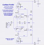
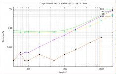
In post #3842 http://www.diyaudio.com/forums/pass-labs/97540-f4-power-amplifier-385.html#post3684975 I showed a schematic and distortion measurements with power rails at +/-24V and +/-32V I was somewhat disappointed with the distortion at higher frequencies so I built low amperage power supplies increasing the rail voltages to +/-45V (I can go higher, but that would require heatsinks for the output MOSFETs).
Below I show the updated schematic and distortion sweeps. The distortion is reduced about by about a factor of 2 vs. the +/-32V measurements. This is largely due to running the MOSFETs at a higher Vds where the Cgd (gate to drain capacitance) is lower and more constant.
The next step to to build a 2nd channel and install these in my F4.
Attachments
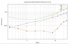
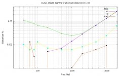
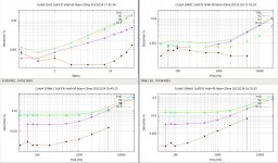
I found a bug in my software that computes THD for the sweep plots. It only affects the THD calculation at low frequencies at levels near the noise floor. The H2, H3, and H>3 plots were correct.
Here are new plots for 50 volt rails and folded cascode current of 20mA plus 5mA for the folded cascode gate voltage divider network.
Wow! These are looking very good. the higher voltages really help.
Here are new plots for 50 volt rails and folded cascode current of 20mA plus 5mA for the folded cascode gate voltage divider network.
Wow! These are looking very good. the higher voltages really help.
Attachments
Those plots were NOT from simulations, but measurements of the PCB in post #3842. http://www.diyaudio.com/forums/pass-labs/97540-f4-power-amplifier-385.html#post3684975The higher voltages do help - if you look at the distortion plots from the BA-3 article, it's quite clear. (makes me want to build a 32V burning amp...)
I love what you doing with this - are you going to build it?
The measurements were made driving about 6 inches of twisted pair to 3 feet of RCA cable to a 10:1 attenuator driving a sound card having a 10k input impedance. Not counting the capacitive load of the wiring, the preamp sees a load of about 33k. I haven't tried it with a 10k load, but it should be fine, just a bit lower output level unless the 1.8k load resistor (R19) is increased. The folded cascode is a transconductance amplifier. The AC output current is the JFET gate AC input voltage times the sum of the transconductances of the JFETs. The output voltage is the output current times the parallel resistance of R19 and the external load.What does it look like driving a 47k,20k , or 10k load using it as a preamp buffer after a tube ? I know that a little off the subject but that's along the lines of the cj evolution that they charged 20k for .
I found a bug in my software that computes THD for the sweep plots. It only affects the THD calculation at low frequencies at levels near the noise floor. The H2, H3, and H>3 plots were correct.
Here are new plots for 50 volt rails and folded cascode current of 20mA plus 5mA for the folded cascode gate voltage divider network.
Wow! These are looking very good. the higher voltages really help.
lhquam.
- Suppose that the center point of the voltage divider is not grounded, and thus is at a virtual 0 VDC.
- Suppose that Vout is then connected to this center point, and its original output load resistor [1.8 K] is not used.
Is there anyone here using 2SK1530/2SJ201??
I run the output using those FET and it seems the bias resistor and pot have to be changed... I can get 0.2V when I change the R9 to 22K and pot increased to 10K... with original value (R9 10K and P1 5K), the bias is stuck at lowest value of 0.8V ( I can increase it but 0.8V was getting very hot so quickly...)..
I'm not sure whether this is a problem or not because haven't test the sound ... just setting up for recommended bias first to see if my heatsink can cope the heat....
regards
- Home
- Amplifiers
- Pass Labs
- F4 power amplifier