Navyblue - An inttermittent DC fluctuations is probably a bad solder joint somewhere. Make sure every solder connection is solid and that nothing wiggles or is soft.
If the amp is biased properly but sounds soft and distorted, the next questions is - what preamp are you using?
If the amp is biased properly but sounds soft and distorted, the next questions is - what preamp are you using?
What I meant by point me in the right direction, is that you tell me what to tell you. ") I want to tell you more but I don't know what else to tell you or to measure.
I want to tell you more but I don't know what else to tell you or to measure.
As far as I can tell, this isn't related to the previous problem. But if you want to know what the previous problem is, the DC at output drifts up and down over time. In the end it was found that the problem went away when the JFET stage is disconnected. So I ordered another pair of JFETs. It took a while to reach and when it did I kinda neglected the project. When I got back to it, the problem went away so I didn't replace the JFETs. Don't ask me why.
I'll post pictures later.
I want to tell you more but I don't know what else to tell you or to measure.As far as I can tell, this isn't related to the previous problem. But if you want to know what the previous problem is, the DC at output drifts up and down over time. In the end it was found that the problem went away when the JFET stage is disconnected. So I ordered another pair of JFETs. It took a while to reach and when it did I kinda neglected the project. When I got back to it, the problem went away so I didn't replace the JFETs. Don't ask me why.
I'll post pictures later.
Navyblue - An inttermittent DC fluctuations is probably a bad solder joint somewhere. Make sure every solder connection is solid and that nothing wiggles or is soft.
If the amp is biased properly but sounds soft and distorted, the next questions is - what preamp are you using?
Thanks.
The preamp is AMB's Beta 22.
The β22 Stereo Amplifier
It can drive headphones, or even efficient speakers directly. So drive capability shoudn't be a problem. Gain is set at 8x. Source is a typical wall powered DAC, I have not measured the output but I imagine it to be the standard 2Vrms. So it should put out 16Vrms. I have the volume set to more than 3/4 but it is soft and crackles and distorts.
Where did you get the Jfets?
The JFETs that are currently installed, I had them for a while from my old projects (that Beta 22). The JFETs that I got but not installed are from a forum member here that sells matched transistors.
Have you listened to headphones through your beta22? Just to make sure it's not the problem?
Regardless, the beta22 has lots and lots of gain and swing, so should be a good match for the F4.
Your Jfet are most very likely genuine...
I'm still thinking that you have a bad solder joint somewhere.
Regardless, the beta22 has lots and lots of gain and swing, so should be a good match for the F4.
Your Jfet are most very likely genuine...
I'm still thinking that you have a bad solder joint somewhere.
Hi RonD2
With the given resistance values, you should be getting:-
voltage across the TL431 should be 5.06V when P1 set to maximum
voltage across the TL431 should be 5.8V when P1 set to minimum
Double check the value of R9, it doesn't look to be 6k8.
R9 is indeed 6k8.
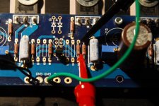
I went back to my “working” channel and powered it up. It is biased cold at 150mV. The voltage across the TL431 as measured in the attached picture is 21 V. Detaching the PS, the resistance across the TL431 is 16.5K.
Tested the problem board in the same setup as above (see pic), the resistance is 21k (responds to P1 adjustment and kept at highest value). Powering it up, the voltage across the TL431 is 21 V. Now there is no measurable voltage across the power resistors in response to P1 adjustment.
I am tempted to “uncripple” it out of desperation. Either that or put it aside for a bit before I do something really stupid.
Attachments
Last edited:
I am tempted to “uncripple” it
I think that's a good idea.
Another possibility is a bias potentiometer with a bad wiper.Have you listened to headphones through your beta22? Just to make sure it's not the problem?
Regardless, the beta22 has lots and lots of gain and swing, so should be a good match for the F4.
Your Jfet are most very likely genuine...
I'm still thinking that you have a bad solder joint somewhere.
Hi RonD2,
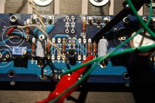
In the second pic, I can see a link in the C1 position, this is not helping if you have fitted a shorting link to the input.
If you do not build the crippled F4 to ZM's recommendations, you will have problems; for the moment, just cut the C1 link, and remove the input shorting link, does this return thing to 'normal' ie. same as the working channel?
In the second pic, I can see a link in the C1 position, this is not helping if you have fitted a shorting link to the input.
Fitting a link in C1 will apply the N FETs gate voltage to the input terminal.....
If you do not build the crippled F4 to ZM's recommendations, you will have problems; for the moment, just cut the C1 link, and remove the input shorting link, does this return thing to 'normal' ie. same as the working channel?
....Looks perfect. But it sounded soft and distorted on both channels....
Do you have another power amp you could try?
First replace the F4, if everything sounds good, you have eliminated the preamp.
Next, there is a simple way to eliminate the JFETs by turning the F4 into a B1; connect the preamp outputs to the F4 inputs, then connect patch leads at the junctions of R3 & R4 and ground wires to the inputs 0V, then connect the (twisted) leads to the inputs of your other power amp; does it sound soft and distorted?
I “uncrippled” both of my F4 boards and have biased both at 120mV cold.
Now that Itsmee has taught me how to measure the TL431, the voltage reading concerns me. Both board’s TL431s measure about 12K R prior to power up. Both boards also measure 16.5V across the TL431 on power up at the 120mV bias. I have not let either warm up.
I have kept the 6.8K R9 resistors.
Should the 16.5V concern me?
Should it not be 9 or 10V + or - ? I would think 16V is excessively high? you have 120mV across a .47 ohm Source R?
Yes. 120mV across the .47 ohm source R. Actually checked them all and they are between 116 and 121 mV.
Wondering if the 6.8K R9 (in place of the 10K original) is, at least partially, to blame for the high shunt voltage?
Yes. 120mV across the .47 ohm source R. Actually checked them all and they are between 116 and 121 mV.
Wondering if the 6.8K R9 (in place of the 10K original) is, at least partially, to blame for the high shunt voltage?
Yes, it could be but, it should be 12.5V or something? Have you measured R8?
What are the voltage readings across D1 & D2 when powered up?
3.9 and 4.1V
- Home
- Amplifiers
- Pass Labs
- F4 power amplifier