M.Pass, what do you think about replacing the bias circuit (TL431) together with the 220uF coupling caps, by a few leds (2 green leds + 1N4148) per side and 2 current sources to bias the leds ? Maybe have you thought in it or even tested it ? Of course the output impedance seen by the mosfet gates will rise (about twice), is it really a problem? The impedance will be constant along the audio range and beyond but lesser than with caps in the lower end.
I don’t know with this particular circuit, but I must say that each time I can avoid capacitors, I get more “transparency”
I don’t know with this particular circuit, but I must say that each time I can avoid capacitors, I get more “transparency”
Justcallmedad said:I don’t know with this particular circuit, but I must say that each time I can avoid capacitors, I get more “transparency”
I don't see C1 and C2 as coupling caps because they hardly interupt any voltage swing.

Nelson Pass said:. . . important that the actual distortion should be minimized. In the case of the original Zen, the second harmonic is large enough at .6% that reducing it gives audible improvement.
We all shocked . . . I really feel sad about . . .
Understood. I didn't go that deep myself yet.
Still, I'm looking for a used distortion analyzer.
I might learn more about the distortion effect later.
Malotron said:I have a question about Veteran's F4 layout : the drain of Q1 connects to P2 and source to R3. Right?Just wondering if I need to flip Q1. Crappy illustration of my question follows below.
-Mal
I don't think so. You have a bottom view of this transistor
")
Nelson Pass said:This version bootstraps the front end so that the JFETs only
see about 1/2 the voltage swing. It improves THD very slightly,
gets a tad more output swing, and it also extends the bandwidth
a bit. With a proper setup, I get about -3dB at 1 MHz, with a
very good looking 100 KHz square wave.
Papa, why 1/2 the voltage swing?
Simply considering R values around?
Thanks.
Nelson Pass said:Why wait - you guys will just start second guessing me in
the meantime.
www.passlabs.com/np/F4R0.pdf
This version bootstraps the front end so that the JFETs only
see about 1/2 the voltage swing. It improves THD very slightly,
gets a tad more output swing, and it also extends the bandwidth
a bit. With a proper setup, I get about -3dB at 1 MHz, with a
very good looking 100 KHz square wave.
Nelson, have you changed your position on bandwidth? As I've said elsewhere, I have found that it takes a solid state piece with around 200-300kHz bandwidth to aproach the subjective ease I can get out of a tube piece with 50-75kHz bandwidth. Obviously, that's not rational, at least on the face of it. I've got some ideas as to why that might be, but they're hardly rigorous.
I'll be interested to follow the F4's acceptance in the marketplace and in the press. I'm curious to see if others react to this circuit with adjectives like ease, air, extension, etc. The problem I've had with using commercial gear as guinea pigs to test my ideas is that wide bandwidth equipment is quite rare. Spectral is the only manufacturer that comes to mind and they don't have wide retail distribution.
And, yes, there may be those who live near radio transmitters who have problems. How common a problem that is will also be interesting to see. Granted, I don't have a lot of RF here, but I've only had problems with one circuit. Given the unity gain and no feedback, hopefully the F4 will be trouble-free.
Grey
Justcallmedad said:M.Pass, what do you think about replacing the bias circuit (TL431) together with the 220uF coupling caps, by a few leds (2 green leds + 1N4148) per side and 2 current sources to bias the leds ? Maybe have you thought in it or even tested it ? Of course the output impedance seen by the mosfet gates will rise (about twice), is it really a problem? The impedance will be constant along the audio range and beyond but lesser than with caps in the lower end.
I don’t know with this particular circuit, but I must say that each time I can avoid capacitors, I get more “transparency”
Richard,
Although I agree in principle with the idea of getting rid of caps, I'm not sure I'm clear as to how you intend to keep the output biased. Given that there will be something like 7-8V difference between the N and P Gates, you'll need to keep them separate. Can you post a schematic?
If I recall correctly, you had posted earlier about using the Vgs of the two inputs to bias the outputs. That would be an elegant solution if you could find JFETs that didn't pinch off by the time the output devices came up to bias. It might be a nifty circuit if you're using lateral MOSFETs as outputs, though.
Grey
Babowana said:why 1/2 the voltage swing?
Simply considering R values around?
I like to minimize bootstrapping, and the 1/2 value works
fine. You could go the full value, but it does create some
peaking up around 1 MZ.
GRollins said:Nelson, have you changed your position on bandwidth?
I'll be interested to follow the F4's acceptance in the marketplace and in the press. I'm curious to see if others react to this circuit with adjectives like ease, air, extension, etc. The problem I've had with using commercial gear as guinea pigs to test my ideas is that wide bandwidth equipment is quite rare. Spectral is the only manufacturer that comes to mind and they don't have wide retail distribution.
And, yes, there may be those who live near radio transmitters who have problems. How common a problem that is will also be interesting to see. Granted, I don't have a lot of RF here, but I've only had problems with one circuit. Given the unity gain and no feedback, hopefully the F4 will be trouble-free.
Let's see....What is my position on Bandwidth?
Oh, I remember. Bandwidth is good unless it's not. By that I
mean that giving consumers a power amplifier with gain and a
very wide bandwith is an invitation to trouble because many
of them (consumers) can't put batteries in a flashlight, much less
do a proper job of grounding in their systems.
Also, bandwidth is good if I get it without having to make a
special effort. As a result my stuff usually gets up to 100 KHz
without any extra parts, so I don't monkey with it.
I have an abstract interest in the acceptance of the F4, but it's
bandwidth is not the part that will influence that - it is the total
lack of voltage gain. It's a surprisingly good sounding piece,
but very few consumers will find that out.
Lastly, since I switched over to FETs, I have not encountered an
instance of RF pickup except for the owner of an Aleph-Ono who
lived in the Empire State Building under the antennae.
Nelson Pass said:
.......except for the owner of an Aleph-Ono who
lived in the Empire State Building under the antennae.
LOL
The ground on his system probably wasn't the best either...
1,250 feet (391 meters) to 102nd floor observatory.
Nelson Pass said:Oh, I remember.
You'll never grow old, Mr P.
What are your thoughts about Mr Rollins's suggestion, including the use of lateral M outputs ?
(Richard, s'il vous plait, j'aimmerai aussi le schema)
jacco vermeulen said:What are your thoughts about Mr Rollins's suggestion, including the use of lateral M outputs ?
Fine with me, but last time I looked they still had greater
THD numbers.
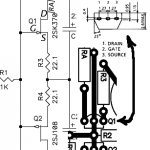
Here a simplified schematic to what I have in mind, more later, I have to prepare diner for my childrens ...
F4 "led bias"
...F4 "led bias"
Justcallmedad said:Here a simplified schematic to what I have in mind, more later,
Interesting. It's quite different concept and approach.
Papa doesn't use current.
Nelson Pass said:I like to minimize bootstrapping, and the 1/2 value works
fine. You could go the full value, but it does create some
peaking up around 1 MZ.
*but* means negative view, which I don't understand.
Minimizing bootstrapping? I don't understand either what should be the optimum value. You are so difficult! Why you don't open the secret? I talk to my boys not to hide tech secret under the table. If they open it, they are better motivated in developing another better thing not to be stay at the same position all the time while the others are growing up.

PS
But, of course, I know I'm talking like a crying baby.
It's very simple. I took what used to be filter caps to
ground and attached them to the output and also
attached the JFET drains to them. This makes the supply
voltages seen by the JFETs and the resistors which feed
current to the bias circuit track the AC output voltage. This
works fine, but it's more AC there than I need, and it results
in a peak in the frequency response up about 1 megaHertz.
If I place a 1K resistor in series with the cap, I still have enough
bootstrap voltage on the Drains of the JFETs, but the peak
goes away.
Nelson Pass said:it results in a peak in the frequency response up about 1 megaHertz.
Phase shift. It's my best guesswork.
Thanks, Papa.
- Home
- Amplifiers
- Pass Labs
- F4 power amplifier