Hi acl0056,
I don't want to hijack this thread, please PM me if you have more questions on that amp.
Both channels should work with one power supply. The additional supply was an upgrade for lower impedance capability if memory serves.
I used to do warranty work for Audio Alchemy. They weren't bad sounding amps, and they seemed to be reliable. Never saw a dead one, but I did have to make bias adjustments on one that ran far too hot.
-Chris
50% music!
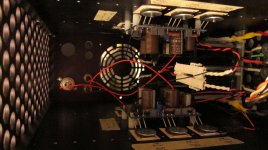
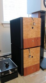
 Love the cases! So clean and compact - for F4s. I am curious to find out how you will mount the transformers.
The case of the Impasse is out of this world. Stunning work.
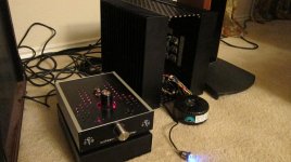
well, tolerances ganged up against me and my front panels don't quite fit. That and drilling into the exact center of the end of a piece of square rod is skill that seems to allude me. Also, I need an odd screw length to affix the bottom half of the fronts, as it seems to be between two sizes and I didn't really tap enough threads in the rod to allow too much length there. Regardless, tonite will be a good night with lots of listening ")
Attachments

It doesn't look like I will be able to fit two channels per side after all. I guess I will have to scratch off the 150 and make it say "OM-25".
I also have a non-working Counterpoint SA-220 amp that I could try using. It should be big enough for four channels, but the heatsinks are optimized for a different type of mosfet package.
I also have a non-working Counterpoint SA-220 amp that I could try using. It should be big enough for four channels, but the heatsinks are optimized for a different type of mosfet package.
Quick question. I have read at least a couple of posts in this thread that suggested the F4 worked best with an 8 ohm load, and that it is perhaps possible that the amp can be pushed into class AB with a 4 ohm load. I have also come to understand that bridging an amp, like what the F4 manual describes as mono parallel operation, halves the load that the amp "sees". Does this mean that the mono parallel or mono balanced configurations could also be pushed into class AB with an 8 ohm load?
Also, to whom it may concern, R24 and R25 are missing from the F4 parts list that I downloaded from the diyaudio store when I bought my boards.
Also, to whom it may concern, R24 and R25 are missing from the F4 parts list that I downloaded from the diyaudio store when I bought my boards.
Also, to whom it may concern, R24 and R25 are missing from the F4 parts list that I downloaded from the diyaudio store when I bought my boards.
Thanks for pointing that out, checking the BOM now.
UPDATE: F4 BOM V1.0a 12/19/2011 is being uploaded.
Thanks!
No problem.
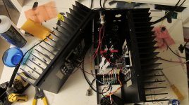
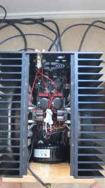
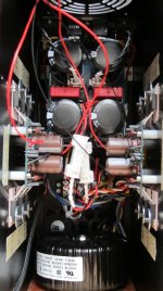
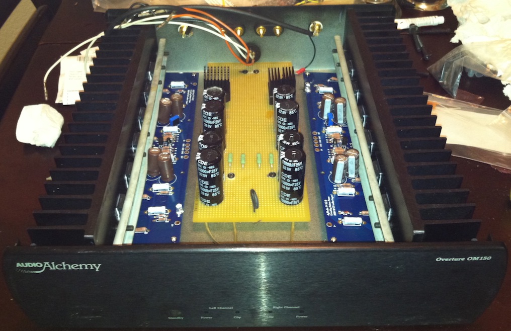
Another update on my end... I have assembled my CRC board. My power transformers (this is one of two amps I am building) are arriving tomorrow. The wife will be away for the night. If all goes well, I should be late for work on Wednesday.
P.S. and before anyone makes fun, yes, those were the cheapest PSU caps I could find. Also, maybe someone could weigh in on whether the rectifier heatsinks look adequate. I really have no idea.
Last edited:
luvdunhill, despite whatever issues you had finalizing your build, it is truly a work of art of staggering beauty. Well done. I hope it has worked out well for you. I assume it has, as we haven't heard from you since your first night of listening.
cheers,
Adam
cheers,
Adam
Last edited:
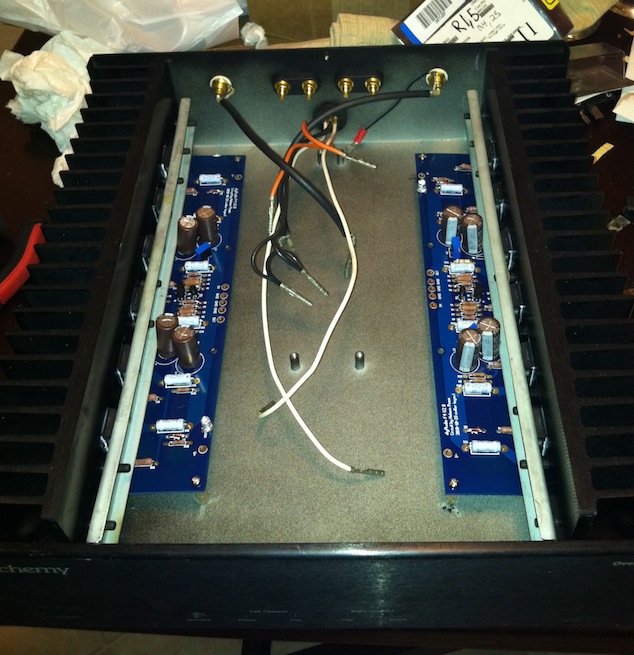
Could seriously use some help here.
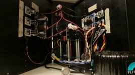
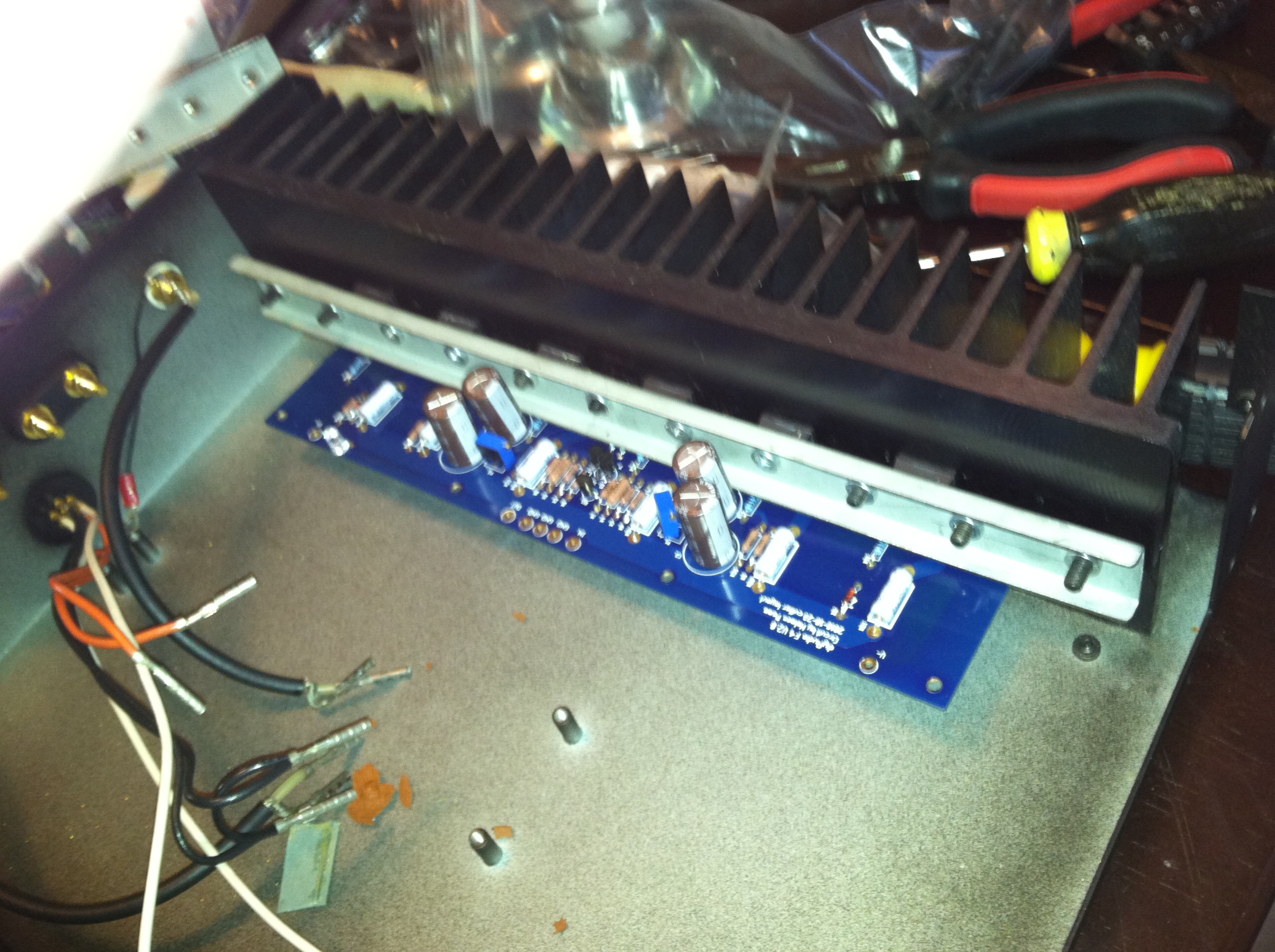
One of these channels was initially not working right, where the PSU resistors started to hum and smoke a little when powering up. Also, the led wasn't coming on. I found that it didn't do that when the bar that clamps the transistors to the heatsink was not attached. I taped up that side of the board. Now when I power it on with it clamped in there, the led comes on, but after a few seconds it shoots sparks from the heat sink to these wires that were set to the side, as in the photo. Is it possible that I damaged the transistors by clamping them too hard?
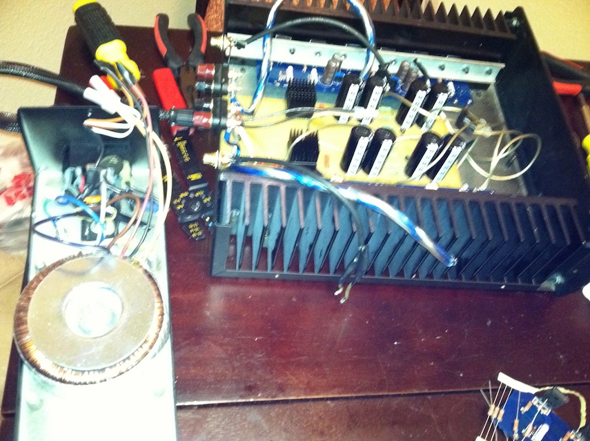
One of these channels was initially not working right, where the PSU resistors started to hum and smoke a little when powering up. Also, the led wasn't coming on. I found that it didn't do that when the bar that clamps the transistors to the heatsink was not attached. I taped up that side of the board. Now when I power it on with it clamped in there, the led comes on, but after a few seconds it shoots sparks from the heat sink to these wires that were set to the side, as in the photo. Is it possible that I damaged the transistors by clamping them too hard?
It sounds amazing. I'm getting a pretty hefty transformer buzz though. It's unclear what is acceptable, but I can make it out from my listening location if the house is quiet. I am also getting some of the same through the speaker and am not sure if it's related. It's of a different pitch, for what that is worth. I have kept the amps on for the past time and they are rock solid stable. I have some headroom for bias, but given the compactness of the build, adjusting things isn't too easy once it is screwed together. I guess that was a minor oversight. I did correct that with the F5 building I'm working on though
One of these channels was initially not working right, where the PSU resistors started to hum and smoke a little when powering up. Also, the led wasn't coming on. I found that it didn't do that when the bar that clamps the transistors to the heatsink was not attached. I taped up that side of the board. Now when I power it on with it clamped in there, the led comes on, but after a few seconds it shoots sparks from the heat sink to these wires that were set to the side, as in the photo. Is it possible that I damaged the transistors by clamping them too hard?
Are the transistors isolated from the sinks with mica or silicon pads ? It's not obvious on the picture...
I guess you already know that, but the case of those FET is electrically connected...
Also , i'd check for connections between the clamp and the FETs.
I would be very surprised that the transistor die would be damaged before the casing shows clear mechanical damage.
Fred
Are the transistors isolated from the sinks with mica or silicon pads?
I used silicon grease from radio shack. So, it would make sense that over-tightening would cause them to short out. Can I find the mica or silicon pads locally? Or, where can I order them?
- Home
- Amplifiers
- Pass Labs
- F4 power amplifier