HOLY CRAP!!!! F4 - BA front end
All I can say is WOW!!!
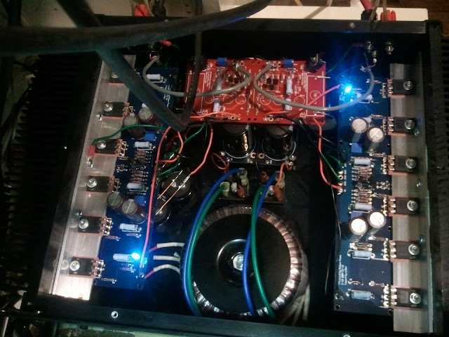
I installed the BA front end into a stock F4...Solen coupling caps, Vishays, Panasonic 3W's, Elna Silmic's...
Pots adjusted to 6.00V per the schematic...
Now THIS is an amp...moderate listening both from ipod-aikido-F4 and LR Source - aikido - F4 have yielded most promising results...
It sounded really good off the Yamaha CA810 as preamp but I think the BA front end sounds better so far...need to get some "alone time" with it to really see...
Nice part is that the BA front end is very small and if it fits in my enclosure it will fit in anyones...
Oh yeah...I also added 44,000uF capacitance per rail...had some caps kicking around...
All I can say is WOW!!!
I installed the BA front end into a stock F4...Solen coupling caps, Vishays, Panasonic 3W's, Elna Silmic's...
Pots adjusted to 6.00V per the schematic...
Now THIS is an amp...moderate listening both from ipod-aikido-F4 and LR Source - aikido - F4 have yielded most promising results...
It sounded really good off the Yamaha CA810 as preamp but I think the BA front end sounds better so far...need to get some "alone time" with it to really see...
Nice part is that the BA front end is very small and if it fits in my enclosure it will fit in anyones...
Oh yeah...I also added 44,000uF capacitance per rail...had some caps kicking around...
Yes I bought some 90deg aluminum angle from home depot and used a miter saw to chop it to length. Drilled and tapped the holes for the MOSFETS. Drilled and tapped the heatsinks.
Used some 220 to smooth the surfaces and applied some thermal grease to the "L".
I really just cranked the heatsink screws as tight as I could, the MOSFETS are "tight"...I am getting only variation of a couple mV per FET so temp spread/dissipation must be pretty good.
Used some 220 to smooth the surfaces and applied some thermal grease to the "L".
I really just cranked the heatsink screws as tight as I could, the MOSFETS are "tight"...I am getting only variation of a couple mV per FET so temp spread/dissipation must be pretty good.
F4 - Components
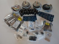
Most of my components have now arrived.
Reading through 3000+ posts in the F4 thread, this is my summary.
Circuit: There is some early confusion on the exact circuit for the F4. The definitive version is labeled "First Watt F4 f0 6/4/07"
BOM: Again there are various versions of the BOM. The definative seems to be by Peter Daniels in post #354.
Circuit Boards: There is one early version by Peter Daniels in a square format. I have used a later version by cviller which arranges the output JFETS in a line. F4 PCB v1.0. I have used these as they are a better fit with my heat-sinks and chassis.
Semiconductors: There are many posts about the use of alternative semiconductors. I have stayed with the standard set available with matched output JFETS from Tech DIY Company Store. I have bought an additional 4 off of the IFRP240 and IRFP9240 output devices to see if I can do any better at matching.
Resistors: All the small signal resistors are 0.5W metal film. I have seen no posts that report on any improvement with exotic resitors, so I have mostly used Vishay CMF55 types from Mouser. Some values are only available in the Mil Spec designation RN55, but as far as I can see, they are the same resistors.
Capacitors: Here there is more debate with some suggestions of Nichicon caps for the 220uf 35V C1-C4 - also with bypass film caps (post # 2020, #2022). In the end NPass comes down definitively on the side of Elna Silmic (post #2047). These are included in the TechDIY kit.
Heatsinks: A topic for many posts. In post #1191 there is a calculation of the thermal requirment in C/Watt. Anything as good or better will do.
Thermal Mounting: There are a number of different solutions for mounting the output devices on the heat-sinks. (Posts #1283, #1641, #1728). NPass favors good old fashoned mica washers with "goop"- thermal paste (Post #1731). Also see post # 2320. If the budget allows, see posts #2737 and #2740 which talk about using copper strips to thermally connect devices over a long heat-sink
Transformers: The FirstWatt F4 uses a 300VA transformer with two 0-18V outputs to generate the +/-23 volt power rails for the stereo pair of F4 amplifiers. Best suppliers are Piltron (USA) and Amlimo (Europe). I have gone completely OTT and bought 2 off 500VA transformers for each mono-block chassis. Each chassis will support 2 x F4 amplifiers in either balanced or parallel mono.
Power Supply: A simple CRC PSU seems the most common option and is used in the FirstWatt F4. Cviller has produced a board for a CRC (see above). I am using 2 boards per chassis, one for each amplifier. Standard caps seem to be 2200uF 35V Panasonic. In post# 2868. NPass suggests that using twice the number of 1000uF, 35V Elna Silmic caps should give a PSU to die for. Being a sucker, I have bought a boatload form DigiKey. There are a number of posts discussing the use of bypass film caps over the main electrolytic's (#2043. #2613, #2615). There is even a whole thread on the subject. It seems that the net-net is to proceed with caution as bypass caps (no matter how exotic) can give rise to high frequency resonances and other problems.
Any comments and corrections on my understanding of "best practice" would be most welcome, especially as I have not started building yet.
PJG
Attachments
The current version of the F4 manual at Firstwatt.com has the correct schematic.
You have CViller's boards - make sure the mod is complete that is detailed on his blog. CVILLER F4 GUIDE
You have CViller's boards - make sure the mod is complete that is detailed on his blog. CVILLER F4 GUIDE
General Information: The F-4 boards currently in the diyAudio Store are laid out by cviller, so pretty much identical (except the mounting holes are different) but have all the corrections made, no modifications are required for these boards. (v2.0). The mounting holes are different so that they will match all the other diyAudio circuit board mounting holes.
Yes V 1.0 needs the mod...V 2.0 is corrected. My boards just purchased from CViller were actually the 1.0 boards. He made the trace cuts on the boards - all I had to do was the connecting of the proper traces. I did not buy from the secret store but directly from cviller.
PJ - just make sure which version of the boards you have.
PJ - just make sure which version of the boards you have.
.......... Standard caps seem to be 2200uF 35V Panasonic. In post# 2868. NPass suggests that using twice the number of 1000uF, 35V .........

Papa standard ones are 15mF/25V Panasonics , 8 per chassis
I'm using 4 of 33mF/25V Panasonic per channel
best bypass caps are motor run caps ( ultra low ESR )
where I have place to put them , I'm using 50 to 80uF ones
best bypass caps are motor run caps ( ultra low ESR )
where I have place to put them , I'm using 50 to 80uF ones
Do you have a manufacture, type or part number for these?
PJG

Do you have a manufacture
If you hand Goldmund $10K for Zeus' 1st wife, you receive one motor run cap for free.

F4 - Cases and Heatsinks
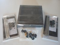
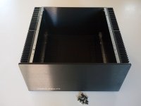
The courier arrived today with two 5U 400mm cases from HiFi200. Great Italian craftsmanship. They are listed as "Pesante Dissipante" which literally translated means "Heavy Dissipater". Well they certainly are heavy - the courier left them on the front step rather than risk a hernia carrying them into the house.
As I suspected, each side heat-sink is in two parts. So now it's off to find some copper strip to thermally connect the six output JFETS.
(I am still worried about the small pile of screws leftover after assembly - never a good sign.)
PJG
Attachments
(I am still worried about the small pile of screws leftover after assembly - never a good sign.)
PJG
not if it were an engine
but in this 'case', who is counting
well - there is a small tweak available for you :
omit output caps on, omit everything in front of two electrolyt caps on F4 input ( tossing out jfet buffer and everything related) , bypassing two elcos with 10-68nF polycarbonats ........ then tell me what's your impression
yeah ....... but only when I'm forgetting fact that I'm spitting image of Modesty Blaze
Modesty Blaise - Wikipedia, the free encyclopedia

Does a power buffer like the F4 benefit from SUSY affect created in Pumpkin FE. Having no V gain does it still benefit from cancellation. Also, any insight into why Nelson uses different buffer on BA amps. Is it just to be able to extend Class A bias further before going into AB?
Does a power buffer like the F4 benefit from SUSY affect created in Pumpkin FE. Having no V gain does it still benefit from cancellation. ...AB?
Yes it does, but only if F4 is included in SuSy feedback loop.
Only for small JFETs (k170/j74), but they are omnipresent anyway...
I suppose you are hunting for the big ones ?
Yeah, looking for the 2sk2103/313. Not really experienced enough to just start building stuff. Would like to see if PSpice says it will not blow up. Oh well. I was going to try the OPA1632 with small F4 or F5 output. may use simpler Jfet FE and try SUSY.
... Not really experienced enough to just start building stuff...
There's nothing much to it: Vgs controls the Id which should be kept under 1A (2A peak if you keep the k2013/j313 reasonably cool). Basic stuff about MOSFETs and three ways to use them are described in Mr. Pass' F5 paper. That's all you need to get started.
Start with simple circuits, use the datasheets, analyze your results and understanding will come. You can't really depend on sims - they won't tell you the whole truth, but they can save you some time by calculating static parameters for you (after you learn how to do that manually).
Knowledge has never been so accessible, you just need to put some effort into it....
- Home
- Amplifiers
- Pass Labs
- F4 power amplifier