jacco vermeulen said:The 70W Pd is not the problem, the Rcs is.
True, but not really an issue for the F4.
I have seen it built with IRF9630F, TO-220 Fullpack, no problems running full throttle.
Magura
")
EDIT: For this to be true, it naturally requires respectable heatsinking.
ch177 said:HI
Nelson Pass
I would like to ask why the function c1 c2? Whether DC blocking it?
If c1 and c2 values will not affect too much the General Assembly high-frequency signal input it?
If I try to c1 and c2 in the 0.1uf capacitor in parallel, what will be affected?
C1 and C2 carry signal and also filter across the bias circuit. The
caps I prefer here are the Elna Silk caps, but you can stick as much
film cap across them as you like.
Re: Elna Silk Capacitors
I have a bunch of the 10 uF @ 25V. In the Digikey catalog they have
1,000 uF @ 35V. It would take quite a few in parallel, but you might
be able to make an awesomely special power supply.
They really are that good...
RobertOder said:What voltage rating(s) do you specify for those beautiful sounding silk capacitors? Do you use the Elnas for all four capacitors or just C1/C2?
I have a bunch of the 10 uF @ 25V. In the Digikey catalog they have
1,000 uF @ 35V. It would take quite a few in parallel, but you might
be able to make an awesomely special power supply.
They really are that good...
Re: Re: Elna Silk Capacitors
Santa,
Have you tried? And now for the dumb non-starter ?, What is the best way to parallel that many caps together?
Chris
Nelson Pass said:
It would take quite a few in parallel, but you might
be able to make an awesomely special power supply.
They really are that good...
Santa,
Have you tried? And now for the dumb non-starter ?, What is the best way to parallel that many caps together?
Chris
Mr. Pass:
I am not sure I understand your response to my question about the Elna capacitors. I was referring to C1/C2 and C3/C4 in the F4 amplifier schematic. Aren't these 220 microfarad capacitors?
I found them here:
http://www.hndme.com/productcart/pc/viewCategories.asp?idCategory=13
I am not sure I understand your response to my question about the Elna capacitors. I was referring to C1/C2 and C3/C4 in the F4 amplifier schematic. Aren't these 220 microfarad capacitors?
I found them here:
http://www.hndme.com/productcart/pc/viewCategories.asp?idCategory=13
RobertOder said:
I use handmade for parts. Very reliable.

Need help troubleshooting - Sorry if this has been brought up before.
Just finished wiring up the F4 and was adjusting the offset & bias -
1 channel was all ok - bias & offset
For the other channel - offset was also ok.
I was also able to adjust the bias via P1, however one of the mosfets (Q5 IRFP240)was running extra hot and was found to have a voltage of 300mv across the 0.47R resistor, Q3 & Q4 are measured at 100mv across the 0.47R during that time. Unable to access R21(Q10 resistor) to measure.
The mosfets are purchased as a matched set.
What are the possible causes for this to occur - how to trouble shoot and rectify.
I do have another set of the F4 boards - should I just use the extra set? (Although it will be a pain to rewire the board and trying to match the tapped holes for the mosfets).
thanks
her shann
Nelson Pass said:It may be that the Mosfets are not matched,
or the resistor is of a higher value than the others,
or the transistors is not well attached to the heat sink thermally.
Heat sink is warmest at the errant mosfet - so i think attachment is unlikely the issue.
Too late over here to tackle this issue - will try another day to resolve it.
thanks
her shann
Nelson Pass said:I would place a larger value resistor on the Source, calculated to
have the same current at the difference in voltage.
PaPa Pass,
thanks for the tip!
After doing some crude calculations - If the voltage across the source resistor is 3x (at steady state) that of the other mosfets - I will have to use a resistor 3x larger (0.47x3).
Is that it? Although I may have to rig up something to test many resistor values, to trial & error.
Thanks, I will report back (in a few days time)
her shann
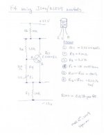
I have been using the F4 for quite some time and still very satisfied with the sound. Since I am able to find some Toshiba mosfets J200/K1529 and thus I have modified the F4 as in attached to use the Toshiba mosfets. I have reduce the source resistor to 0.245 ohm (0.51//0.47) due to good match of the mosfets. Below is the modification I did on the bias circuit.
The sonic of Toshiba mosfet is more refine to me especially on the mid and high frequencies.
Spencer
The sonic of Toshiba mosfet is more refine to me especially on the mid and high frequencies.
Spencer
Attachments
A late builder
Should I read all the long discussion? OK I will, well I am actually, but am I allowed to ask for two questions?
1) What size for the H/S? I could recycle a pair rated at 0.33 C/W. Enough?
2) I am going for a choke input PSU (as I have a +35VAC transformer), any hint on the current each channel requires?
Thanks
Gianluca
- Home
- Amplifiers
- Pass Labs
- F4 power amplifier