bubba177 said:has anyone had a hum problem with the F4?
I had such hum problem, first with Son Of Zen, then with f4. Solution:
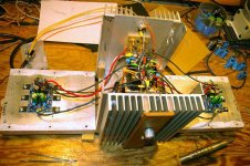
I always use longer cables to have possibility to manipulate with heatsink and to move position of cables inside amplifiers - it really helps. Very useful are good headphones instead of loudspeakers or voltmeters - you can easy find minimum of hum. The only problem is to keep cables at the position - result looks not elegant, but is effective.
I will try to attach a picture.
a.
Hi !
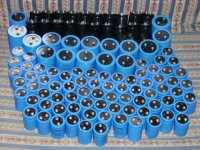
Only 2

He he, Look!
Regards zeoN_Rider
Manu said:
Did you already make this PSU?
Manu
I bought this red cans recently... are they good?
Only 2
He he, Look!
Regards zeoN_Rider
Attachments
Re: Hi !

naah ........ I know that you'll not keep them all ;
so - keep low profile .........
zeonrider said:
Only 2
He he, Look!
Regards zeoN_Rider
naah ........ I know that you'll not keep them all ;
so - keep low profile .........
Troubles...
Hello folks... Today I thought I had finished my work, but it seems like I was wrong
Initially, once fired up, it suddenly blew the fuse. I checked my wiring, looking for something wrong, and I didn't find anything. I moved the amplifier, put an another fuse to see what happened, and it did work... I started with my BIAS regulation, and found the 250mV across the 3W resistors for both channels... I was just waiting for it to warm up (for the hot BIAS tuning), and I moved the amplifier under the lamp; while moving it, I stopped hearing the "bzzz" from the toroid, and the fuse was dead again. I assumed that something was near the aluminium cabinet walls (grounded), and it touched them while moving the amp. I moved some resistor pins, some of my wire, and blew about 15 fuses in the trial-and-error procedure. Finally, the only possible candidate I discovered was a little pin under the boards, a little too long, which could have touched the heatsinks. I cut it, put the amp back together, fired it up again and it worked.
Now, the real problem arised: I made two mistakes, the first was letting the OUT wires (speaker +) touch the cabinet: a very nice spark and "pop". The second one, while trying to measure the BIAS across a resistor, was shorting said resistor towards ground (a damned screw) with my tester plug. An another spark, very bright and powerful indeed, and I said "oh well, maybe I should start doin' something right".
The issue is the following: now, in my left channel, while I turn my BIAS trimmer, I can get nowhere past 60-70 mV across power resistors. The regulations goes well until 60-70, then, even if I keep on turning, the voltage remains stuck there. In the right channel, instead, I can't get anything but 0V, no matter how hard I turn that trimmer.
I measured between V+ and V- on both boards, and I read about 22 V (But, being +/-23V, shouldn't I read about 46?).
I really can't figure out what I've broken... I'm no expert at all. If anyone could understand what happened, I would really appreciate. Remember that, before those "accidents", the first time I turned it on I was able to get 250mV across the power resistors in both channels.
Thank you very much...
EDIT: OK, I don't know if it's the only issue, but I have a V+/ground voltage of 4V. I checked it because my LEDs weren't turning on anymore. I think something in my PSU got KO...
Giacomo
DaveM said:I would start by looking at the diodes in the power supply. Disconnect the amp from the power supply and verify that you are getting (+23)-0-(-23). If you are not seeing those voltages without load, you have likely toasted the power supply diodes.
I edited my post just while you answered me; it really seems like you say. I tried measuring direcly on my right rectifier bridge, but, as I put the tester plug on the "+" terminal, I have a huge spark...! What's up? I specify that the other plug was still in air, without touching anything.
Very confused with it, any suggestions about "how to measure across a rectifier bridge without obtaining a lightning"?

Giacomo
Hi Giacomo
Given the background information regarding the connection of only one
lead of the multimeter and assuming a battery powered (floating) multimeter.
Assuming that the bride were not damaged.
Could it be that the positive terminal on the bridge rectifier were not making proper contact with the wire which connects it to the capacitors
The act of measuring the voltage disturbed the connection on the positive terminal on the bridge which led to the sudden connection of the terminal to the capacitors this would have resulted in a spark due to the sudden current spike as the capacitors charged up .
Re: Hi !
You're right... BTW are you sure you need them all?
Manu
zeonrider said:
Only 2
You're right... BTW are you sure you need them all?
Manu
Re: Re: Hi !
Aha, I, like blue color!
Regards zeoN_Rider
Manu said:
You're right... BTW are you sure you need them all?
Manu
Aha, I, like blue color!
Regards zeoN_Rider
DaveM said:Good to hear you got it running. Now how does it sound?
Don't know, that's why I'm excited...
It's still on the table, warming up, I go sometimes to check it and adjust BIAS to 250mV across the 3W resistors (hoping it's right to randomly choose one of them - the most confortable one - and keep 250mV across itself, to have the proper BIAS...).
Giacomo
DC on outputs
Dave, what do you use to test this? I use computer speakers, but don't own a dummy load. Any recomendations to measure without potentially blowing up a driver?
DaveM said:Most importantly, make sure there is no DC on the outputs. We don't want any melted voice coils
Dave, what do you use to test this? I use computer speakers, but don't own a dummy load. Any recomendations to measure without potentially blowing up a driver?
Re: DC on outputs
Well, I know I'm not Dave.......
You just measure voltage across the speaker terminals, using your favorite multi-meter
Magura
mithomas said:
Dave, what do you use to test this? I use computer speakers, but don't own a dummy load. Any recomendations to measure without potentially blowing up a driver?
Well, I know I'm not Dave.......
You just measure voltage across the speaker terminals, using your favorite multi-meter
Magura

- Home
- Amplifiers
- Pass Labs
- F4 power amplifier