I think with DIY we may realize a better way in this regard. Nelson, thanks for bringing this forward [/B]
Continuing on with that line of thought...
Now we could run a BIG signal from the preamp (front end?), and put the attenuator in the output stage chassis (F4). This would attenuate the noise on the cables as well.
Neat design as usual, Nelson. Thanks for sharing it with us.
Is it bootstrapping that is enabling the nearly rail-to-rail swing?
yes, interesting isn't it?
good thought NS
A unity gain power <amplifier> with a stepped attenuator at the input, preceded by a high voltage non adjustable linestage/ or source......
Thats out of the box
")
Edit: You could even make it seem conventional so you don't reach for the volume at the amp under the rack or on the floor. You could take a twisted pear Joshua Tree type relay attenuator and put the pot in the linestage chassis, then implement the relays in the <amp>. A simple 3 wire jumper between the two for control.
good thought NS
A unity gain power <amplifier> with a stepped attenuator at the input, preceded by a high voltage non adjustable linestage/ or source......
Thats out of the box
Edit: You could even make it seem conventional so you don't reach for the volume at the amp under the rack or on the floor. You could take a twisted pear Joshua Tree type relay attenuator and put the pot in the linestage chassis, then implement the relays in the <amp>. A simple 3 wire jumper between the two for control.
nobody special said:Is it bootstrapping that is enabling the nearly rail-to-rail swing?
There isn't any bootstrapping in this version.
Nelson Pass said:
There isn't any bootstrapping in this version.
Mr. Pass,
You're killing me!
Is it the jfet front end? Isn't there usually a need for 3.5V or so more volts swing than the output rail (each rail) to get it to swing all the way?
Very interesting design.
mpmarino,
I'm thinking about building an X front end using a folded cascoded differential pair running on 80V rails to drive a pair of these bridged. Should be very similar to a commercial pp X-amp, I would think. If I remember right, Nelson has said before that the pp X series doesn't use feedback on the output stage.
Jason's post regarding:
Any boards available for this project?
/Hugo
Any boards available for this project?
Has been moved to : http://www.diyaudio.com/forums/showthread.php?goto=newpost&threadid=99351jleaman said:Has any one got any boards for this amplifier, id like to buy a set to try this amp out, i think i have adequate heat-sinks too.
J'
/Hugo
nobody special said:Is it the jfet front end?
I think that the jfets are doing just one thing--providing high input
impedance. So, I see F4 as one stage 0dB-gain amp. As simple as
it should be . . . I can't read Papa's mind tho . . .

> I think that the jfets are doing just one thing--providing high input impedance.
And also a low output impedance to ensure high bandwidth for the power MOSFET follower.
> So, I see F4 as one stage 0dB-gain amp.
Spot on. But whether it is one stage depends on whether you define a follower as a stage. The JFEts essentially form a complememntary unity-gain impedance converter.
Patrick
> By the way, I considered F4 as an amplifier of current gain.
I thought about using that term, but then the gain is dependent on output impedance, which is reactive for a power amp. So I thought I stick to using the term Follower.
PS Following Peter Daniel's comment about the F3, I am thinking that I can couple the (digital) source directly to the input of the circuit in post #185, and perform volume control at the 100R 4W resistor before the 3rd stage (shunting it by a 0R1 resistor would give 60dB). I need to get rid of the 2x 39Rs and replace them each with a magnified diode (using e.g. a TL431 or a BC550).
Patrick
well I am ipressed. if there any diferent with proac 2.5(which is verry fuzzy and untransaprent with low resoliution ) i think I find a new competitor to my 4fets xa 20 .steenoe said:Hi Tony
The rails run at about 22V DC, but I didnt take an excact reading.
Its all about apples and pears, allright, but I have no doubt, the F4 is the best sounding amp, that I have ever made/heard! My A-X's are about to be under heavy modification
Thats how amazing the F4 is! Drop all your other projects, and go straight to the F4! Beleive me, you wont regret it
Steen
we will build we will see. thanks NP as always for sharing circuits for DIY comunity 
Hi there,
I'm glad that with F4 Mr. Pass gave us a circuits that betters the Aleph (I believe Steen when he says so - there is probably no circuit in this forum that he did'nt build and/or critically listened to).
The thing that keeps nagging at me is that we have been repeatedly told over the years that push-pull topology is something unnatural and that it should be avoided. Zen 5 was an exception with no significant echo in community, but it was a circuit with a voltage gain (MOSFETS in common source connection).
Suddenly there is a plain complementary buffer that surpasses all the single-ended designs we had in the past (Alephs, Zens, Firstwatts).
I enjoy my Aleph amp very much (although I build it out of sheer curiosity) and I will build the F4 for the same reason, but I'm very confused with this sudden change of stance towards push-pull.
Please Mr. Pass, can you shed some light on this ?
P.S. I don't believe that you didn't try the circuit in figure 1. from Zen 5 article in that time.
Attachments
This is exactly the circuit mr. Pass has put to use in F4. The bias is provided with the resistor network arround the TL431 and the DC Shift (ofset) of the signal is fed through the coupleing caps. This DC shift is normally done by taking the driving siglnal outside a resistor pair. thus reducing the possible voltagesving of the amplifer. Personly i think this is one of the unique elements in this design. We only need a Jfet pair that can handle a larger voltage sving. So let's invent a 100 V jfet pair, so we can make a +50 V version.
Attached is a revised input circuit with 24 dB gain and changed jfets so voltage can be raised a little.
Attached is a revised input circuit with 24 dB gain and changed jfets so voltage can be raised a little.
Attachments
juma said:The thing that keeps nagging at me is that we have been repeatedly told over the years that push-pull topology is something unnatural and that it should be avoided. Zen 5 was an exception with no significant echo in community, but it was a circuit with a voltage gain (MOSFETS in common source connection).
Suddenly there is a plain complementary buffer that surpasses all the single-ended designs we had in the past (Alephs, Zens, Firstwatts).
I enjoy my Aleph amp very much (although I build it out of sheer curiosity) and I will build the F4 for the same reason, but I'm very confused with this sudden change of stance towards push-pull.
Please Mr. Pass, can you shed some light on this ?
Well, I don't think I told you those things. I like single-ended
circuits for their simplicity. Others have explained the appeal
of SE circuits by speculating that 2nd harmonic sounds less
offensive than 3rd.
The Zen and F series have been exploratory from my viewpoint,
and one of the benefits of this has been the conclusion that
people don't necessarily prefer 2nd over 3rd harmonic, in fact
many times people prefer 3rd harmonic.
I offer as examples the common preferences of the BOSOZ
over the BOZ, and the sound of the F1 over the F2. None have
negative feedback, but the former circuits are "balanced single-
ended" and the latter purely single ended. The former have
3rd harmonic, and the latter 2nd harmonic, otherwise they
are very similar in parts and execution.
What to make of this? First we should note that "balanced SE"
circuits have intrinsically less distortion through cancellation of
2nd harmonic, usually about 1/5 the distortion. This might
be adequate to explain the F1/F2 preferences, but less likely
to explain the BOSOZ/BOZ as the BOZ still has about 1/10
the distortion of an F1.
So I continue to go about my business, designing up circuits
and listening to them. If I ever discover the real secret to
this, I'll never tell.
AD said:I also don't understand why on earth did you move this post away to the Trade area?
Perhaps it was intended to stimulate availability of the boards.
An F4 board run is likely inevitable. We can only be glad Jason started the fire and giving him a separate thread will surely encourage others to make it happen. Any discussion of board production or sale can now take place there. I’ll gladly move it to group buys if needed.
/Hugo
I’ll gladly move it to group buys if needed./Hugo
Carpenter, good idea.
I updated the post:
http://www.diyaudio.com/forums/showthread.php?postid=1174260#post1174260
/Hugo
I updated the post:
http://www.diyaudio.com/forums/showthread.php?postid=1174260#post1174260
/Hugo
Ah yes, Captain Flints!
Went there for my thirteenth BD... wrestled a burger about the size of my head!
We only need a Jfet pair that can handle a larger voltage sving.
Have you tried the 2sj105/2sk330 pair? 50vdgs
-Mal
The problem with using higher voltage JFETs is that you run into heat dissipation problems if you don't back off on the current. The problem with backing off on current is that distortion climbs because you have trouble driving the cumulative Gate capacitance of the outputs.
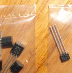
What we need are good TO-220 case JFETs that can take more than 3-400mW of heat.
And while I'm at it, I'd like to request some nice TO-247 JFETs, too.
Silly of me, I know, but I've always been a dreamer.
Grey
P.S.: I gave Hint #1 for modifying the F4 elsewhere. I now drop...
Hint #2: Parallel lower Idss devices for the input complementary follower. Don't have BL? Use two or three GR, or whatever.

Yeah, and people keep saying Japanese parts are easy to get here...
(Same thing I've run into--you have no say in whether you get GR, BL, or VI...[of course, the VI are analogous to the Nonesuch])
You may find that the parallel JFETs have their own capacitance increase. It's workable. See Hint #1.
Grey
(Same thing I've run into--you have no say in whether you get GR, BL, or VI...[of course, the VI are analogous to the Nonesuch])
You may find that the parallel JFETs have their own capacitance increase. It's workable. See Hint #1.
Grey
- Home
- Amplifiers
- Pass Labs
- F4 power amplifier