Hello,
This testing procedure is for use with a digital multimeter in the diode test-range with a minimum of 3.3 volt over d.u.t. (diode-under-test).
Connect the 'Source' of the MosFet to the meter's negative (-) lead.
1) Hold the MosFet by the case or the tab but don't touch the metal parts of the test probes with any of the other MosFet's terminals until needed.
2) First, touch the meter positive lead onto the MosFet's 'Gate'.
3) Now move the positve probe to the 'Drain'. You should get a 'low' reading. The MosFet's internal capacitance on the gate has now been charged up by the meter and the device is 'turned-on'.
4) With the meter positive still connected to the drain, touch a finger between source and gate (and drain if you like, it does not matter at this stage). The gate will be discharged through your finger and the meter reding should go high, indicating a non-conductive device.
Such a simple test is not 100% -- but is useful and usually adequate.
When MOSFETS fail they often go short-circuit drain-to-gate. This can put the drain voltage back onto the gate where ofcourse it feeds (via the gate resistors) into the drive circuitry, prossibly blowing that section. It will also get to any other paralleled MosFet gates, blowing them also.
So, if the MosFets are deceased, check the drivers as well! This fact is probably the best reason for adding a source-gate zener diode; zeners fail short circuit and a properly connected zener can limit the damage in a failure! You can also add subminiature gate resistors -- which tend to fail open-circuit (like a fuse) under this overload, disconnecting the MosFet's gate.
Best regards,
Kristijan Kljucaric
http://web.vip.hr/pcb-design.vip
Attachments
thank you for the explanation for measurements irfp 240
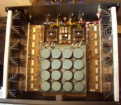
I try to build a aleph 2.
I wanted to know if it was necessary to put 2 inductors of 3.9mh. one for -
one for +
I use 4 X 33000 uf 63 v if it's the case can - you to tell me which inductor I have to use precisely?
escuse my english !!!!!!!!!!!
I try to build a aleph 2.
I wanted to know if it was necessary to put 2 inductors of 3.9mh. one for -
one for +
I use 4 X 33000 uf 63 v if it's the case can - you to tell me which inductor I have to use precisely?
escuse my english !!!!!!!!!!!
Nice Site you have - with PCB-service
kristijan-k
Nice site you have - http://web.vip.hr/pcb-design.vip/
With great information for Pass-builders.
Plus PCB-service for the projects.
Perfect resource for Pass DIY-selvers!
halojoy - checking the members homepages
kristijan-k
Nice site you have
- http://web.vip.hr/pcb-design.vip/With great information for Pass-builders.
Plus PCB-service for the projects. Perfect resource for Pass DIY-selvers!
halojoy - checking the members homepages
Attachments
I wouldn't particularly advise that you use the method described by kristijan-k. You can use the Vgs matching procedure shown at www.passdiy.com that will not only tell you if the devices are working, but you can also match them at the same time.
more expansive article on testing MOSFETs
at PASSDIY - "Practical MOSFET Testing for Audio"
http://www.passdiy.com/pdf/mos.pdf
at PASSDIY - "Practical MOSFET Testing for Audio"
http://www.passdiy.com/pdf/mos.pdf
- Status
- This old topic is closed. If you want to reopen this topic, contact a moderator using the "Report Post" button.