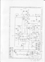
ok after undergoing a lot frustration and thinking what amp to do and asking i hope not annoying ppl with posting and asking, i finally decided to do an aleph 3.
i attached a file where i've redrawn the schematics a little to fit my needs. so i did some searching and found most answers.
so i did the following changes:
1) change irf244 to irfp240
2) change mpsa18 to BC550C
3) downgrade trafo to 160va(maybe 220va) 2x18-0,erase connection +thermistor(both) between the two channels and c1-c8 to 10k uF to use aleph3 in dual mono
so now to annoy ppl even more than i did some questions:
4) aleph3 needs to be 25°C above ambient to operate properly? how critical is this temperature? (as i use active cooling with fan speed controlled it should not be such a problem, except if heatsinks are way too small, but i hope not") )
)
5) i am not that sure about the connection points as there are not any marked at all on the schematic, i think i got it right but just for sure i marked them on the attached file - as i am afraid to blow exp. parts otherwise
6) the value of the D? where it says VAL, but this is only to show if the amp is on, isnt it?
7) mosfet matching: so can anyone tell me how critical it is to match the irfp240? as i don't have money to burn (well who has...), so how many devices i got about to buy? (i know it depends but some estimation would be great, is it 10 or 40 ?) as they cost 3€ from distrelec or 5€ from farnell
8) the pins where it said src and out, i dunno what they should be for!
ok, hope to annoy ppl not too much and not take your time. sorry for bad grammar. i will post pics to the gallery as a reward =] and if wanted add these answers to the wiki, so ppl dont have to ask again(for parts etc...).
thanks and regards
Patrick
redrawn picture:
i attached a file where i've redrawn the schematics a little to fit my needs. so i did some searching and found most answers.
so i did the following changes:
1) change irf244 to irfp240
2) change mpsa18 to BC550C
3) downgrade trafo to 160va(maybe 220va) 2x18-0,erase connection +thermistor(both) between the two channels and c1-c8 to 10k uF to use aleph3 in dual mono
so now to annoy ppl even more than i did some questions:
4) aleph3 needs to be 25°C above ambient to operate properly? how critical is this temperature? (as i use active cooling with fan speed controlled it should not be such a problem, except if heatsinks are way too small, but i hope not
)5) i am not that sure about the connection points as there are not any marked at all on the schematic, i think i got it right but just for sure i marked them on the attached file - as i am afraid to blow exp. parts otherwise
6) the value of the D? where it says VAL, but this is only to show if the amp is on, isnt it?
7) mosfet matching: so can anyone tell me how critical it is to match the irfp240? as i don't have money to burn (well who has...), so how many devices i got about to buy? (i know it depends but some estimation would be great, is it 10 or 40 ?) as they cost 3€ from distrelec or 5€ from farnell
8) the pins where it said src and out, i dunno what they should be for!
ok, hope to annoy ppl not too much and not take your time. sorry for bad grammar. i will post pics to the gallery as a reward =] and if wanted add these answers to the wiki, so ppl dont have to ask again(for parts etc...).
thanks and regards
Patrick
redrawn picture:
Attachments
It's you again!
Dear Patrick,
3) Methinks 160VA will be too little, because the amp draws a minimum of 100W per channel, all the time, day and night. So I'd go with 300VA at least. Maybe I got you wrong and your intetion is to have a seperate tranny for each channel. Then 160VA each should do fine. In this case you could probably lower the supply's capacity. Otherwise the supply voltage may drop if too much current is drawn from both channels. I'd strongly recommend CLC or at least CRC filtering (F1 or Zenlite for an example).
The thermistor on the primary side is very useful, as it limits inrush current. These little things work wonders. If you have a tranny with dual primaries and use it on 230V you can use a thermistor to connect them (again, F1).
4) As far as I remember, there's something about the distortion-figure or something.
5) It might help to have a look at the MiniA schematic, it
's more simple (but basically the same). You'll see things like C101 going to ground, drain of Q102 going to -V,...
6) The diode is an indicator, yes. It should not be blue because there are already too many of them. I think red might work best.
Besides, take a look at the F1 service manual, it employs a nice way to dim the LED.
Earth:
Earth ground the mofo via a thermistor, seriously. The thermistor keeps it from directly seeing earth and helps damping some small currents if any loops occur via power-connections and interconnects between different pieces of your equipment. If something happens, the thermistror's resitance (better say inductance) will drop immeadiately, keeping things safe or at least something close to safe.
Ground:
Have one point (or one copper bar) where all the PSU-capacitors' grounds meet =: {A}
Have one single point per channel where all the audio-circuit's grounds meet (four components and the inputs' minus go to ground only, so that's easy) =: {B_left, B_right}
Now have one point where A, B_left, B_right, Out_minus_L, Out_minus_R are connected to. This is der sternförmige massenpunkt, ja. This point will be earthed via the thermistor. The chassis, if you're using something conductive, can be earthed directly (this would be the other leg of the thermistor, chassis and line-earth).
Don't use the point you've called 'GND' to connect any ground of the audio circuit because large current pulses of the supply will be present there.
And use fuses BEFORE the switch, right after the line filter. And don't call me whilst I'm driving.
Please, anyone, tell me if I got something wrong somewhere, especially regarding the grounding and earthing routine.
Dear Patrick,
3) Methinks 160VA will be too little, because the amp draws a minimum of 100W per channel, all the time, day and night. So I'd go with 300VA at least. Maybe I got you wrong and your intetion is to have a seperate tranny for each channel. Then 160VA each should do fine. In this case you could probably lower the supply's capacity. Otherwise the supply voltage may drop if too much current is drawn from both channels. I'd strongly recommend CLC or at least CRC filtering (F1 or Zenlite for an example).
The thermistor on the primary side is very useful, as it limits inrush current. These little things work wonders. If you have a tranny with dual primaries and use it on 230V you can use a thermistor to connect them (again, F1).
4) As far as I remember, there's something about the distortion-figure or something.
5) It might help to have a look at the MiniA schematic, it
's more simple (but basically the same). You'll see things like C101 going to ground, drain of Q102 going to -V,...
6) The diode is an indicator, yes. It should not be blue
because there are already too many of them. I think red might work best.Besides, take a look at the F1 service manual, it employs a nice way to dim the LED.
Earth:
Earth ground the mofo via a thermistor, seriously. The thermistor keeps it from directly seeing earth and helps damping some small currents if any loops occur via power-connections and interconnects between different pieces of your equipment. If something happens, the thermistror's resitance (better say inductance) will drop immeadiately, keeping things safe or at least something close to safe.
Ground:
Have one point (or one copper bar) where all the PSU-capacitors' grounds meet =: {A}
Have one single point per channel where all the audio-circuit's grounds meet (four components and the inputs' minus go to ground only, so that's easy) =: {B_left, B_right}
Now have one point where A, B_left, B_right, Out_minus_L, Out_minus_R are connected to. This is der sternförmige massenpunkt, ja. This point will be earthed via the thermistor. The chassis, if you're using something conductive, can be earthed directly (this would be the other leg of the thermistor, chassis and line-earth).
Don't use the point you've called 'GND' to connect any ground of the audio circuit because large current pulses of the supply will be present there.
And use fuses BEFORE the switch, right after the line filter. And don't call me whilst I'm driving.
Please, anyone, tell me if I got something wrong somewhere, especially regarding the grounding and earthing routine.
thanks dave for your answers =]
well about the grounding. maybe i did draw some things too fast (as for the switch^^), but i think i'll manage that... if i am in doubt i can ask a friend of mine called david bayer, think he's here on the forums too.
160va would be for mono as the schematic shows. and i think i am gonna use a blue led, as i got some of them left laying around here waiting to be used by some smart, good looking, cool guy.
i am quite sure about 1) and 2), just wanted someone to confirm this.
4), 5), 7) & 8) i am a bit concerned about.
to 5): i did look at the aleph mini schema, but i cant figure out all of those by myself
to 7): i think a lot of money can be wasted/saved here, so i hope someone can give me experience and i will turn out lucky =]
to 4) most important besides 5) 7) and 8) =] well at least 8 i think i can ignore that and answer yes to myself.
btw, as mentioned, i can do a wiki about the construction, maybe not helpfull for most ppl here, but maybe for some "news".
thanks & regards,
Patrick
1) The IRFP240 will be fine.
2) Most any NPN will work. You're just using the Vbe to run the Aleph CCS. As long as the part has a sufficient voltage rating, it'll do the job. There's no appreciable current to worry about.
3) As a rule, think 6X the rated output power for an Aleph, but don't obsess over it. 30W x 6 = 180VA. 160VA is a little scant, but should be okay, particularly if you use a fairly beefy part, such as a Plitron transformer. A cheap salvage part might need a little extra cooling if it runs warm. An 18V transformer will give you roughly 23V rails.
4) I water cool a pair of Aleph 2s and they're barely warm to the touch. Don't worry about the temperature so much as the voltage and current that run through the device. They're the primary determinants. The actual operating temperature is much further down the list.
5) Nelson uses what I call the Foresthill dialect of schematic-ese. If two lines cross, they don't connect. When Nelson wants them to connect, he shows them as a T, not a +. If you want to build Nelson's stuff, you'll need to become fluent in the Foresthill dialect.
Small price to pay.
6) That's the power LED, traditionally blue for Pass gear. You can do whatever you want. I generally put the power LED from the positive rail to the negative rail (with an appropriate resistor) just to make sure both draw down...sooner or later. Using an LED and resistor as a bleeder lets you know when the caps have discharged.
7) Match 'em.
8) Don't worry about SRC and OUT. They're just there to confuse the unwary.
Grey
ShanaVar said:
5) i am not that sure about the connection points as there are not any marked at all on the schematic, i think i got it right but just for sure i marked them on the attached file - as i am afraid to blow exp. parts otherwise
Surely I would be in doubt too, so hope this helps:
Aleph 3
Aleph 3 psu
- Status
- This old topic is closed. If you want to reopen this topic, contact a moderator using the "Report Post" button.