I built a aleph mini with boards from KK some time ago. The amp sounds amazing, but I found that when I used the positive (non-inverting input) there was a phase lag in the left (aka bad) channel. When I use the negative (inverting) input, there is no phase lag at all.
Attached is my oscilloscope output of this (I hope, I am new to using this forum). The sinewave is 20kHz and the vertical is set to 5V/ division. Both channels are fed the same signal via a y-splitter connected to the positive inputs. As you can see, there is a clear lag in the phase of one of the outputs. This goes away when I feed the negative inputs. The unused inputs are shorted to ground.
I have tried the obvious:
changed the output mosfets (irf 634's)
changed the NPN transistors
it was a long time ago, but I believe I changed the input mosfets
I am pretty sure I changed the CCS mosfet, but again, this was over a year ago
I swapped the input wires back and forth, and fed the board directly (not through chasis mounted RCA inputs)
All the voltages are similar for both channels, I will post when I get info onto the computer.
Some things that might be significant:
I did just realize that I have an IRF9630 input CCS mosfet on the channel with no variation, and an IRF9510 input CCS mosfet on the channel with the phase lag -- could this be producing a different bias current in the two channels to the input mosfets?
I changed the bias setting resistors (in series with the output gain and CCS mosfets) from .33 ohm to 1 ohm -- they show a .66 V voltage drop across each
I crammed a terminal block onto the board's input holes. It is nor really sized for this. Could I have made some capacative connection on the input that is causing the phase lag?
I plan on getting out the 'iron this weekend and trying some more changes. My ultimate plan is to cascode the input mosfets with jfets, but I want to work this problem out first...
Attachments
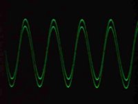
jupiterjune said:Attached is my oscilloscope output of this (I hope, I am new to using this forum). The sinewave is 20kHz and the vertical is set to 5V/ division. Both channels are fed the same signal via a y-splitter connected to the positive inputs. As you can see, there is a clear lag in the phase of one of the outputs.
I think that the different phases mean the voltage gain difference between the left and right channels caused by the different locations of the upper critical frequencies to the same test signal. The most probable reason seems to be that the capacitances of the plus input side MOSFETs are different between the left and right channels.
The reason why I say this is that I can see the different V peak2peak values from your scope screen.
Re: Re: Aleph-phase lag with non-inverting input
I think the voltages are just shifted vertically to illustrate the difference...
Have you tried to switch your probes and channels on scope? What is the bandwidth of your scope?
I'm not sure about the CCS transistors if they supply the same constant current, the difference shouldn't matter, but I guess the 630 might supply much more current unless you have made some adjustments. I think a higher current through you diff pair would give you a higher corner frequency. You could try to swap them or put in some identicals.
Try to measure if you have the same current through the diff pair on both channels.
Babowana said:
The reason why I say this is that I can see the different V peak2peak values from your scope screen.
I think the voltages are just shifted vertically to illustrate the difference...
jupiterjune said:
I did just realize that I have an IRF9630 input CCS mosfet on the channel with no variation, and an IRF9510 input CCS mosfet on the channel with the phase lag -- could this be producing a different bias current in the two channels to the input mosfets?
I changed the bias setting resistors (in series with the output gain and CCS mosfets) from .33 ohm to 1 ohm -- they show a .66 V voltage drop across each
I crammed a terminal block onto the board's input holes. It is nor really sized for this. Could I have made some capacative connection on the input that is causing the phase lag?
I plan on getting out the 'iron this weekend and trying some more changes. My ultimate plan is to cascode the input mosfets with jfets, but I want to work this problem out first...
Have you tried to switch your probes and channels on scope? What is the bandwidth of your scope?
I'm not sure about the CCS transistors if they supply the same constant current, the difference shouldn't matter, but I guess the 630 might supply much more current unless you have made some adjustments. I think a higher current through you diff pair would give you a higher corner frequency. You could try to swap them or put in some identicals.
Try to measure if you have the same current through the diff pair on both channels.
Gray-
The input mosfets are the same in both channels, IRF9510's. They were matched fairly closely for Vgs for another project, but I don't have the exact numbers--I will check if I end up removing them.
Cviller-
You are correct about the traces being offset vertically to show the phase difference, they sort of fuzz together otherwise. When I switch the feed to the negative (inverting) inputs it is clear that he lag is gone.
I am not sure that the input CCS mosfets are supplying the same current, they both have app. 10volts on their gates. __I will try puttting a little more voltage on the gate of the input CCS mosfet tonight--it should then pass more current....
Measuring the current through each individual mosfet in the differential pairs seems impossible--I will post the voltages I get once a get a circuit dwg to attach
PrestonTom, Cviller-
I am 99% certain it is not in the probes or scope, but I will check it again tonight. If I switch the feeds to the neg. input, it will disappear. It should stay gone if I then switch the probes on the output--I will recheck this. After that, I will switch channels that the RCA connections from y-splitter are feeding and repeat. I don't remember the bandwidth of the scope--I will check and post. I think it is a B&K.
Bobowana-
The outputs are offset vertically. The gain is essentially the same for the two channels at 20KhZ. At 100KhZ, I think I noticed the bad (left) channel had a little less gain, and the offset was definitely much greater.
Also, I can try using the capacitance meter on my fluke DMM to see if I can read a capacitance in the input circuit...(did not think of this before)
I have my list of things to re-check tonight!
Is your offset in the "bad" channel positive or negative? If negative, then you might have more current through your diff pair in that particular channel - at least that is how it works in my fishamp.
If you short the input, I think you can get a relative estimate of the current by looking at the voltage over the resistor connected to one of the legs of the diff pair.
If you short the input, I think you can get a relative estimate of the current by looking at the voltage over the resistor connected to one of the legs of the diff pair.

Well, I just finished double checking the probes and inputs. The phase lag remained unchanged in the left channel when the positive inputs were fed. It disappeared as expected when the negative inputs were fed.
I measured some voltages:
Positive supply rail +18.99 volts
Negative supply rail -19.00 volts
There is a 220 ohm resistor in series with the source of the input CCS mosfet:
on right(good) channel +18.99 volts in and +13.51 volts out, which should be a current of 24.9ma,
the gate of the input ccs mosfet for this channel has +10.18 volts on it, and the drain of the input ccs mosfet has +2.93 volts
on left(bad) channel across the 220 ohm resistor : +18.99 volts in and +13.10 volts out, which should be a current of 26.7ma
the gate of the input ccs mosfet for this channel has 10.07 volts on it, and the drain 2.9 volts.
There does not seem to be anything significant there.
I rechecked the gain at 100kHz, it is down slightly in the bad channel, I can post a picture perhaps tomorrow. The difference was maybe .2 volts -- I will need to look closer to give a more accurate reading on that.
Is this simply due to a different input capacitance of the two mosfets, or poorly matched Vgs?
I is late(for me!) -- I will post more info hopefully tomorrow.
and Nelson, yes it sounds amazing -- Thank you for your generous contributions to the DIY community!
update
Well, I have a brief update on this problem.
I changed out the 9.1 volt zener diode that supplies reference voltage to the gate of the input CCS with a cermet pot. This let me change the app. 27ma bias current through the input mosfets to see what happened.
The first thing I found was that the output waveform collapsed when the bias current was dropped to only 22ma.
By checking the DC voltages with a DMM and looking at the ac waveform at different points in the circuit, it appears as though the Vgs of the noninverting input mosfet is app. 2.9 volts, wheras the the Vgs for the inverting input seems to be about 2.6V. The left (bad) channel is operating with noninverting input mosfet nearly off.
I went back to my notes when I tested the 9510's, and it just said "all have Vgs of app 2.6". (I was building an A75, matching for these devices was not critical).
I think I can fix the problem by increasing the bias current though the input ccs to app. 40ma (haven't tried it yet), or I can solder out the input mosfets and get a better matched pair. It would be interesting to see if correctly read the vgs of the two devices.
Of course, all the above could be wrong, I will keep you posted.
I am working on drawing up the circuit, I will post with notes of my observations so anyone interested can see how I came to those conclusions.
I vote for pulling the devices and putting in a matched pair, rather than a simple increase in bias, which will open a can of worms. The "on" device will dissipate a great deal more heat than the "off" device, for instance.
You'll also get better performance from a matched pair. Distortion will be lower.
While you're at it, it wouldn't be a bad idea to pull the front end out of the other channel and see how closely they're matched.
Grey
You'll also get better performance from a matched pair. Distortion will be lower.
While you're at it, it wouldn't be a bad idea to pull the front end out of the other channel and see how closely they're matched.
Grey
I think I will have to pull them just out of curiosity to see how well the "in place" measuring of Vgs worked.
The additional current actually seemed to be making both devices work better (moves them both into their linear operating ranges perhaps) -- the one device wasn't completely off, just closer to being off so that it seems to be causing the phase lag.
I plan on running the higher current through the input devices anyway,--maybe the amp will be more detailed. This was just a 'spare parts' amp, to decide if I should build another a-75 or an aleph-X, but it ended up sounding so good, I put that project on hold.
I tried upping the current through the input CCS, and now the amp is humming along -- literally--it now has hum in both channels. And the phase lag remains.
Things that have changed that could be possible causes:
1) I replaced the 1 ohm resistors in series with the output mosfets with .66 ohm resistors. PS ripple went from 50mv to 80mv.
2) I used a resistor current divider network on the gates of the input CCS mosfet, as opposed to a zener diode. They now have app.
3) I put press-on heatsinks on the input mosfets.
4) The hum could possibly be psychicly transferred from cvillers fishamp.
Does anyone know if any of the above are known to induce hum?
jupiterjune said:I tried upping the current through the input CCS, and now the amp is humming along -- literally--it now has hum in both channels. And the phase lag remains.
Things that have changed that could be possible causes:
1) I replaced the 1 ohm resistors in series with the output mosfets with .66 ohm resistors. PS ripple went from 50mv to 80mv.
2) I used a resistor current divider network on the gates of the input CCS mosfet, as opposed to a zener diode. They now have app.
3) I put press-on heatsinks on the input mosfets.
4) The hum could possibly be psychicly transferred from cvillers fishamp.
Does anyone know if any of the above are known to induce hum?
Increasing the front end bias will not solve your problem. Use matched MOSFETs.
I'm not surprised the ripple increased...you've increased the bias in the output. This increased the load on the power supply, which in turn leads to greater ripple. Read the voltage drop across the Source resistors in the output stage.
While the resistive divider may not perform as well as the Zener in setting the front end current source, the CMRR of the differential should reject the ripple passed through from the rail...assuming that the differential MOSFETs are matched (ahem).
Grey
jupiterjune said:1) I replaced the 1 ohm resistors in series with the output mosfets with .66 ohm resistors. PS ripple went from 50mv to 80mv.
More ac current gain,
more possibility of hum.
The phase lag lives forever,
not harming the sound.

- Status
- This old topic is closed. If you want to reopen this topic, contact a moderator using the "Report Post" button.
- Home
- Amplifiers
- Pass Labs
- Aleph-phase lag with non-inverting input