Hi
I thought it would be better to start a new thread with my problem. Perhaps I'm not the only one struggling with hum.
http://www.diyaudio.com/forums/showthread.php?postid=1119626#post1119626
I have built a different version of Zen Mod's babbelfish, with two pairs of output transistors. It sounds very good (I had it working without noise for some reason), but now I have problems removing the noise and adjusting the bias.
I have tried to connect all ground wires the same place, but that didn't fix my problem. I have also swapped all bjt's and tried removing c102.
My supply is a crc with 2x15mF->0.2R->4x15mF and my ripple is +/- 25mV with one channel running, but I want to use it to power both channels. The output ripple is 10mV
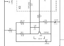
I have attached my schematics with measured values and I have some pictures of my setup here:
http://viller.org/audio/2007jan_jfish/hum/
Please tell me if I need to supply more information. I have a 60MHz scope.
Questions:
How much ripple should it be able to reject?
Is my supply simply too tiny? (I do however have 90mF per rail while aleph 3 has 88mF)
Do I have any fundamental errors in my schematics?
How do I fix it?
I thought it would be better to start a new thread with my problem. Perhaps I'm not the only one struggling with hum.
http://www.diyaudio.com/forums/showthread.php?postid=1119626#post1119626
I have built a different version of Zen Mod's babbelfish, with two pairs of output transistors. It sounds very good (I had it working without noise for some reason), but now I have problems removing the noise and adjusting the bias.
I have tried to connect all ground wires the same place, but that didn't fix my problem. I have also swapped all bjt's and tried removing c102.
My supply is a crc with 2x15mF->0.2R->4x15mF and my ripple is +/- 25mV with one channel running, but I want to use it to power both channels. The output ripple is 10mV
I have attached my schematics with measured values and I have some pictures of my setup here:
http://viller.org/audio/2007jan_jfish/hum/
Please tell me if I need to supply more information. I have a 60MHz scope.
Questions:
How much ripple should it be able to reject?
Is my supply simply too tiny? (I do however have 90mF per rail while aleph 3 has 88mF)
Do I have any fundamental errors in my schematics?
How do I fix it?
Attachments
cviller said:Hi
I thought it would be better to start a new thread with my problem. Perhaps I'm not the only one struggling with hum.
http://www.diyaudio.com/forums/showthread.php?postid=1119626#post1119626
I have built a different version of Zen Mod's babbelfish, with two pairs of output transistors. It sounds very good (I had it working without noise for some reason), but now I have problems removing the noise and adjusting the bias.
I have tried to connect all ground wires the same place, but that didn't fix my problem. I have also swapped all bjt's and tried removing c102.
My supply is a crc with 2x15mF->0.2R->4x15mF and my ripple is +/- 25mV with one channel running, but I want to use it to power both channels. The output ripple is 10mV
I have attached my schematics with measured values and I have some pictures of my setup here:
http://viller.org/audio/2007jan_jfish/hum/
Please tell me if I need to supply more information. I have a 60MHz scope.
Questions:
How much ripple should it be able to reject?
Is my supply simply too tiny? (I do however have 90mF per rail while aleph 3 has 88mF)
Do I have any fundamental errors in my schematics?
How do I fix it?
adjusting the bias?
if you have problems with that-just decrease slightly R124 in your schematic
I see that you now have similar currents per mosfet ; what was issue? mosfet or resistor?
you must tell us now how you made supply .
mebbe diode bridges are tiny....... or you need to rearrange CRCs
hi
technical details for my normal A3 with irf9610
-one transfo for both channels + 2 x 35A bridge +2 x 68000uF
-after separate LC sections for right and left
-total cap 408000uF +4 x 1.2mH
-25 v rail and 2A bias
-power supply ripple is 25mV
-hum is very low on output
-oversize heatsink for around 40C to 45C after 3 hrs
-exactly 50% ac gain
-just to check your power supply my supply ripple for both
channels 4A is also 25mv ac and just a small hum on
(92db speaker) no problem so your supply seem ok
-maybe a ground loop so if you remove all input what
happend to hum on speaker and also ground input
-maybe transfo magnetic induction so ?? try
to isolate with metal sheet
-when you said "problem to adjust bias" same problem
for me my aleph ccs was unstable but with 1nF cap
on base and collector q103 (mpsa18 in normal A3)
it s ok now
bye
Re: Re: Hum problem with jfet Aleph 3 (babbelfish)
I changed the mosfets.
I have two toroids with 10x17V at 1.5 each. I use two 25A bridges (one for each rail)
http://pdf1.alldatasheet.com/datasheet-pdf/view/111065/ETC/FB2506.html
capacitors are in total 12x15000uF
Sorry - I meant biaspoint or dc offset.Zen Mod said:
adjusting the bias?
Zen Mod said:
I see that you now have similar currents per mosfet ; what was issue? mosfet or resistor?
I changed the mosfets.
Zen Mod said:
you must tell us now how you made supply .
mebbe diode bridges are tiny....... or you need to rearrange CRCs
I have two toroids with 10x17V at 1.5 each. I use two 25A bridges (one for each rail)
http://pdf1.alldatasheet.com/datasheet-pdf/view/111065/ETC/FB2506.html
capacitors are in total 12x15000uF
jeapel said:hi
technical details for my normal A3 with irf9610
-one transfo for both channels + 2 x 35A bridge +2 x 68000uF
-after separate LC sections for right and left
-total cap 408000uF +4 x 1.2mH
-25 v rail and 2A bias
-power supply ripple is 25mV
-hum is very low on output
-oversize heatsink for around 40C to 45C after 3 hrs
-exactly 50% ac gain
-just to check your power supply my supply ripple for both
channels 4A is also 25mv ac and just a small hum on
(92db speaker) no problem so your supply seem ok
-maybe a ground loop so if you remove all input what
happend to hum on speaker and also ground input
-maybe transfo magnetic induction so ?? try
to isolate with metal sheet
-when you said "problem to adjust bias" same problem
for me my aleph ccs was unstable but with 1nF cap
on base and collector q103 (mpsa18 in normal A3)
it s ok now
bye
Thanks for your data - makes me think I might be able to work this out.
I just tried to see if a metal plate between psu and amp changed anything, but nothing changed on the scope.
Re: Re: Re: Hum problem with jfet Aleph 3 (babbelfish)
Hi
Is the rated VA of trafos sufficient? Seems some tinny.
Cheers
cviller said:
I have two toroids with 10x17V at 1.5 each. I use two 25A bridges (one for each rail)
http://pdf1.alldatasheet.com/datasheet-pdf/view/111065/ETC/FB2506.html
capacitors are in total 12x15000uF
Hi
Is the rated VA of trafos sufficient? Seems some tinny.
Cheers
cviller said:
Thanks for your data - makes me think I might be able to work this out.
I just tried to see if a metal plate between psu and amp changed anything, but nothing changed on the scope.
seems irrelevant - if I conclude OK-that you have hum even in breadboard variant,where toroid was miles away from main pcb
if then you haven't hum.......there is a culprit
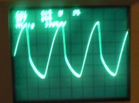
I think I might have found the error - or at least I have found something which is wrong. The CCS regulation seems to be oscillating insanely. I took a picture (with my left hand - sorry!) of the scope output. I'm looking at the node connected to basis of Q103 and R133,R125 and R123.
The scope is set to 5V and 2us
The scope is set to 5V and 2us
Attachments
Have you solved the ripple problem yet?
I have a mini-aleph built using KK's boards, and I have absolutely no noise whatsoever.
However, I have noticed, especially with my A-75, that I get noise associated with shorting the unused input to signal ground. Since there is a 5ohm resistor in parallel with diodes connected to earth ground, there is some residual voltage there that gets put into the input that the other channel does not see -- hence, it gets amplified. It goes up when I turn up the bias.
I see from your diagram that you saw some ripple on the input shorted to ground (app 1 mv) but none on the other one. It would then make sense this would be amplified to the outputs. You might want to see what happens if you use a much lower resistance to ground on both channels (say 10 or 20 Kohms0) and don't connect the unused input to ground. This should put the same small amount of hum on both inputs, which will then be rejected as it is common-mode noise.
How is your PS signal ground to earth ground made? Is it with a resistor in parallel with diodes, or is it through an inrush surge arrestor?
JJ
jeapel said:did you try 1nF on base and collector
the official aleph 30 design has 1nF
and it s work in my aleph 3
I just quickly tried it, and it seemed to remove the oscillation, but it did nothing to the ouput - still humming away.

jupiterjune, thanks for your suggestions, I'll try that. Shouldn't I also change the other resitors (R103 and R104) to avoid changing the gain?
My psu is not grounded to earth.
Too bad the 1nF did solve my problem - I had high hopes for that one.
I have run some simulations where 25mV ripple on psu maps to less than 500uV on output, so I'm quite sure that I have a problem with my setup which cannot be explained by psu alone.
I tried run the amp with both inputs open, and that gave me less noise on output cos not having signal or gnd on balanced minus takes away the gain and so the amp is more quiet, but also kinda makes the amp useless. When inputs are shorted, the resistance to gnd is only 22k through input resistors.
I have removed the zeners, but that didn't help either.
jeapel said:i check my setup this morning
with 92db speaker
-with my irf9610 aleph 3 i hear no hum with 50cm max. from bass speaker
If everything is quiet I can easily hear hum from cheap old akai speakers.
-have you a radio or music from satellite or whatever
with a earth ground
The inputs are shorted and not connected to anything.
-the last thing try to put more cap on + and - 25volt ???
Perhaps that's the only solution, but if one channel hums with 90mF per rail I'm afraid I'll need close to 1F in total.
Edit: And 25mV ripple on rails shouldn't be a show-stopper according to what NP says about Aleph 3 an 30.
maybe ???
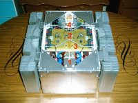
see the photo
no. 1 big capacitor ground 6cm wide
no. 2 big PCB ground 1,5cm wide
no.1 and no.2 together with big no. 8 wire
no. 3 input ground directly on no. 2 big ground
no. 4 speaker ground directly on no. 2 big ground
interconnect from mosfet to PCB with no. 14 wire
see the photo
no. 1 big capacitor ground 6cm wide
no. 2 big PCB ground 1,5cm wide
no.1 and no.2 together with big no. 8 wire
no. 3 input ground directly on no. 2 big ground
no. 4 speaker ground directly on no. 2 big ground
interconnect from mosfet to PCB with no. 14 wire
Attachments
cviller-
I am no expert on power supply designs, but my understanding is that the signal to earth ground is critical -- probably for both safety and to prevent your signal ground from "floating". When I built my amps I spent a lot of time reading about power supplies. One website that has a lot of info is elliot sound projects, ESP. The web address is http://sound.westhost.com. Read project 4, "power supply for amplifiers".
He shows the connection of signal groung being made to earth ground though two diodes in parallel with a 10ohm resistor, but I have found that using the inrush surge supressor works much better. I think the details on that were first presented the the BZLS article by NP.
I hope Rod Elliot isn't a dirty word or "persona non grata' on the Pass Labs forum....
jupiterjune said:cviller-
I am no expert on power supply designs, but my understanding is that the signal to earth ground is critical -- probably for both safety and to prevent your signal ground from "floating". When I built my amps I spent a lot of time reading about power supplies. One website that has a lot of info is elliot sound projects, ESP. The web address is http://sound.westhost.com. Read project 4, "power supply for amplifiers".
He shows the connection of signal groung being made to earth ground though two diodes in parallel with a 10ohm resistor, but I have found that using the inrush surge supressor works much better. I think the details on that were first presented the the BZLS article by NP.
I hope Rod Elliot isn't a dirty word or "persona non grata' on the Pass Labs forum....
For safety reasons earth is a good thing, but in my apartment it is nothing different than the neutral wire, except it is connected on the other side of the HFI relay (shuts of everything when a few mA runs through instead of the correct way through fuses). And my amp is not yet in a case - only placed on heatsink. Some people just cut the earth wire if they have problems with ground loops on between earthed equipment (might be dangerous and is obviously the wrong solution to that problem), but I'm only looking on one amp and nothing else.
cviller-I can't get what is wrong with your amp ,at least not from information you gave;
if you look on blur images in babelfish thread- my babel proto was just a mess of parts and wires in one hetasink........no PtP jobie,just a mess ;
with two 33mF cans ,one 25A diode bridge (hanging in air) ........350VA underpowerd toroid (underpowered via variac,just because xformer is on full voltage 2x33Vac) I don't have any hum or tizzz or buzzz even on 92+db/W/m speaker...........talking all the time about one channel prototype ............
leave it for few days; do some other thing,then (we) try again......
read "Zen and motorcycle maintenance" in meantime
- Status
- This old topic is closed. If you want to reopen this topic, contact a moderator using the "Report Post" button.
- Home
- Amplifiers
- Pass Labs
- Hum problem with jfet Aleph 3 (babbelfish)