I am seeing 62.7 + and - when I measure with power applied.. When I remove power the cap on the left (the newer cap) drains to like 52v in a few seconds.. the one on the right (older) drains very slowly.. like 61v in same time span.. WHAT DOES IT ALL MEAN?! ")
Steve; I think the side with all the mis matched #'s is the GOOD side..! I have the other side disassembled now.. (see pics) the resistors on the back of the "hot side" are all toast.. every one of the big ones.. cracked.. but all else looks perfect.. it looks like this i orginal.. I so no signs of repair.
Not sure if this will display but...
I'll follow your links and read more..
this is starting to get fun.. but only because I have help.. else it would be no fun. I'll see if I can get the good channel tested today. yikes.
Steve; I think the side with all the mis matched #'s is the GOOD side..! I have the other side disassembled now.. (see pics) the resistors on the back of the "hot side" are all toast.. every one of the big ones.. cracked.. but all else looks perfect.. it looks like this i orginal.. I so no signs of repair.
Not sure if this will display but...
An externally hosted image should be here but it was not working when we last tested it.
I'll follow your links and read more..
this is starting to get fun.. but only because I have help.. else it would be no fun. I'll see if I can get the good channel tested today. yikes.
One other thread worth keeping an eye on is the following. The guy is repairing an old Phase Linear piece and much of the advice given so far is worth considering in your case as well:
http://www.diyaudio.com/forums/showthread.php?s=&threadid=95035&perpage=10&pagenumber=1
http://www.diyaudio.com/forums/showthread.php?s=&threadid=95035&perpage=10&pagenumber=1
barchetta said:I cant' edit and I cant send a message to the moderator.. All I need to do is add a bracket to the image but I can't.. I am I that much of an a$$ that I am still under moderation?!

The bracket is fixed.
All new guys are in moderation, that's a standard procedure. You will be unmoderated in due time.
Regards,
Milan
Apogee said:One other thread worth keeping an eye on is the following. The guy is repairing an old Phase Linear piece and much of the advice given so far is worth considering in your case as well:
http://www.diyaudio.com/forums/showthread.php?s=&threadid=95035&perpage=10&pagenumber=1
Yes; sounds like its the sam darn thing..
thanks to moderator for fixing my image.. useless as it is.. I am just proud its out.. the heatsink is slightly warped but I dont think it will be a problem..
It's a pain in the rear because the system only lets us edit messages for 30 minutes before it casts them in concrete.
The mods will eventually reply to the "report" button at the bottom of each post or you can try emailing them directly.
Since everything is volunteer, sometimes it takes a while for folks to respond if they're not at their computer.
I just ran into the same thing regarding the Phase Linear post I just made. I had wanted to include it in my original reply but was unable to - hence the second post.
moamps said:
The bracket is fixed.
All new guys are in moderation, that's a standard procedure. You will be unmoderated in due time.
Regards,
Milan
Cept I could edit before.. I am being re-assimilated. LOL
barchetta said:Cept I could edit before.. I am being re-assimilated. LOL
Irrelevant. We are the Moderator.
Carry on...

You might consider checking the bridge rectifier like I posted earlier.
The caps draining at different rates with nothing hooked up to them could just be that one is old and one is new. Also could be a bad diode in the bridge. Remember what I emailed about leakage on old caps? This is where the LCR meter I mentioned comes in handy. We have no idea how old the "new" one really is. There should be date code on them that will give an idea.
Anybody else have an opinion on this????
Based on what you've posted regarding most if not all of the emitter resistors being cracked, that tells me that the power supply also took a pretty good hit when it was cooking all of that stuff. Usually if something is going to go, it will be part or all of the bridge...
You know, stepping back and based on what I've seen so far, I would be very tempted to completely go through both channels of this thing. Since the other channel has mixed outputs already in it anyway, it might be worth considering a true going through. That means:
new hexfred bridge
new main filter caps with more capacitance (better bass)
new dale resistors throughout
all new outputs that are from the same lot (and matched if possible) on both channels
caddock or mills on the emitter resistors
all new small signal transistors
new small signal panasonic or black gate caps
possibly new input (don't look like teflon in the pics) and speaker terminals if it needs them
Cardas wire from the inputs to the boards and the outputs to the speaker terminals
When you're finished, this thing would be the best it could be...
Athsetically it's not perfect but it's not in bad shape. You could even have the heatsinks and front panel re-anodized (you'd lose the threshold screening on the front panel) while it's apart. Front panel might clean up pretty well, it's hard to tell from the pics. Then the thing would look brand new...
I don't know if you just want it fixed or want to tweak it to the nth degree while you're at it. Also, how much you want to spend on it.
It's just something to think about.
I don't know what I want to do.. but Might be best to get my hands on every part I can find (and order 1 for each side) and see what happens when I rebuild the one side.. see how they sound together.. make sense?
I'll start by looking for the tough to find transistor you mentioned and I'll also check the rectifier..
Have not tried the "good side" yet for 2 reasons.. one was I had to apply daylight savings time patches to my mail servers at work.. (did you know its changing this year?) and 2.. I want to be sure about hooking up the wires.. I got all of em but one.. and its obvious but I am a bit timid.. the actualy positive output to speaker.. I assume it gets connected on the inside of the output fuse? So lesse..not on the fuse to terminal but the other side of the fuse.. I cant see where he desoldered that one.. I know sounds silly but I'd rather have a successful "smoke test" this early in the game. My confidence would be crushed!
-Joe
P.S. can't thank you guys enough.. I have learned SOOO much already.. my Porsche project is suffering but its too cold out anyway.
Thinking further about rebuilds...
I know I'm going to get flamed for this for desecrating a classic... LOL!
The thought just occurred to me that since you might be considering a complete rebuild anyway, why not turn it into an Aleph?
It would be very easy to do using Peter's boards here:
http://www.diyaudio.com/forums/showthread.php?s=&threadid=92577&perpage=10&pagenumber=1
You already have a case designed for class A use (2/3rd's of the battle). The only question is if the transformer has 220 volt primaries (to build an Aleph 30) or if not, you would need to scale it up to an Aleph 2.
You could even have the front faceplate laser etched with the PassDIY logo and then rebrushed and anodized. It would look killer!
Since you already have a 400a anyway, this would give you another Pass amp to try for not much cost.
I think it could be done in a manner that was fully reversible if you ever wanted to. (assuming no faceplate work)
Guys, thoughts on this??????????
Joe,
I know I'm hitting you lots pretty fast. We're in no hurry here and it's all about having fun...
Regarding your smoke test, you might consider putting a light bulb in series with the power cord. This will keep most of the magic smoke in if something else is bad on the other channel. This would be wise to do at least for the first attempt. It will still allow you to measure for DC at the output but not have the unit at full power.
The other option would be a variac.
Also, if you considered grabbing a soldering/desoldering station it would make your life MUCH easier:
http://cgi.ebay.com/PACE-PPS80A-MBT...QQihZ019QQcategoryZ109556QQrdZ1QQcmdZViewItem
http://cgi.ebay.com/XYTRONIC-988D-D...QQihZ002QQcategoryZ109556QQrdZ1QQcmdZViewItem
I dont know what a aleph is or how it compares to what I have.. I'll try and figure out what the answer is to that..
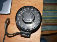
Actually; I own a very nice variac.. heheheh I KNEW it would come in handy one day! I'll connect it up and bring it up slow..
If I were to convert the 400a to something else the only part I might have to modify would be the aluminum heat sink that the PCB is connected to.. and then it would just be drilling and tapping the holes.. so I could hang on to the original PCB's in case it would need to be brought back from the dead..
But I still dont know what the conversion would cost and/or what it means quality-wise...
I think you could actually get away with even using the same aluminum piece without modifying it. I initially thought the same thing regarding either drilling it or just making a new one.
But, I went back and looked at your pics closely. I think you could mount the replacement board in the same spot as original (just make some brackets) and use the existing screw holes from the TO3 outputs to anchor the new fets.
You'd just run wires to the board rather than mounting the fets to the board itself.
The only difference if you have to scale it up to an Aleph 2 would be more fets and changing a few resistor values.
The question is whether or not the 400a transformer has 220v primaries??? This is only important if you want to build the smaller Aleph 30.
You'd know by looking where the power cord comes into the unit. See if there are a couple of leads on that terminal board that aren't hooked up to anything.
As far as quality goes, consider this - all of Nelson's current gear uses FETs as output devices...
I think it would cost less than repairing the 400a and you'd have a better sounding amp to boot!
There are wires under the transformer that are just snipped and have some shrink tube on the ends so they do not short... good sign?
I am off to his site to try and understand all of this..
EDIT: from the top of the xformer:
WESTERN
CODE 377
WTI NO 2199B
PRI-100v=WHT-Gray
12v=WHT-BLK
SEC-88v6a BLUE-BLUE
646av6a Blue-Black
I am off to his site to try and understand all of this..
EDIT: from the top of the xformer:
WESTERN
CODE 377
WTI NO 2199B
PRI-100v=WHT-Gray
12v=WHT-BLK
SEC-88v6a BLUE-BLUE
646av6a Blue-Black
You guys are going too fast for me, and I was left back at
page 3.
From Barchetta's photo of the rear panel we see that the
output RC network has been fried. This would be due to either
a fool with a square wave generator, or more likely due to
the output of the amp being allowed to bleed back to the input,
forming an oscillator at about 100+ KHz. We used to see a lot
of this sort of thing in the old days usually due to bad grounding
on the input interconnect wires, and is one of the primary reasons
I tend to roll off amplifiers above 100 KHz.
In any case, we know the likely cause of the damage. I think we
want to remove the damaged channel and replace the output
devices and emitter resistors. I repeat - I don't think matching
is necessary, but if you want to be fancy, test the beta (current
gain) of the devices and use the high beta devices on the output
and not the cascodes.
You can get the schematic for the later units at www.passlabs.com/np
You have an early unit which is distinguished mainly by fewer
output devices.
Meanwhile I suggest that you buy a Variac (not the moderator)
for cheap (try Marlin P Jones) as you will find it very useful now
and in the future, and prepare to run some tests on the good
channel using a multimeter (Radio Shack).


- Home
- Amplifiers
- Pass Labs
- Repair question re: threshold 400a