I want to remoove output capacitors from pass D1 IV stage?
is it possible technicaly? how to do this? I am using originaly fully balanced d1 stage like original.
any thought on this?
I am using passive Preamp with balanced DACT 20Kohm, there is no capacitors in power amplifiers at input or output ,and no output capacitors in DAC no capacitors.
sorry for my humble question..
Attachments
If I were you ...
If I were you, I would be looking at a folded cascode instead as a starting point as it will save you one gain stage + allow direct feedback between input and output if desired (some minimal filtering perhaps). There should be plenty of references on this board.
I am surprised it hasn't been done already, I guess capacitor outputs are "safe" whereas DC coupled outputs gone awry easily damage other equipment.
(/begin rant) Unfortunately, many outputs of preamps are AC coupled as are many power amps. One barrier should be enough, but now one has two (/end rant)
Petter
I don't see any mechanism to keep DC offset under control; no feedback, etc. You might be able to finagle the thing to get the output to 0V, but then you'd have to deal with thermal drift. At a guess, it will take a complete rebuild of the back end. Not that it can't be done, but there'll be more to it than clipping the leads and removing the caps.
Grey
Grey
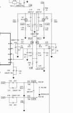
You mean something like this... except that R2/R13/R8/R14 are replaced with a 50k pot to adjust the input voltage level, and R15/R16/R18/R19 are replace with a pot to adjust the output voltage level.
Something I've built but haven't had a chance to properly test yet, but the basic idea is there.
Cheers, Terry
Something I've built but haven't had a chance to properly test yet, but the basic idea is there.
Cheers, Terry
Attachments
metalman said:You mean something like this... except that R2/R13/R8/R14 are replaced with a 50k pot to adjust the input voltage level, and R15/R16/R18/R19 are replace with a pot to adjust the output voltage level.
Something I've built but haven't had a chance to properly test yet, but the basic idea is there.
Cheers, Terry
If anybody is asking me, yes this is the topology I was suggesting. Let us know how it turns out!
thanks very much I will investigate in this. I dont mind a problem with dc ofset .my amps has pretty big ofest even after warm up  luckily current my dac has dc ofset trimmer.
I think I can handle 1-5mV in DAC.
I tested lot of electrolytic and metalysed polyster r or polipropylene, silver.gold foil in oil polypropylene, paper in oil aliuminium,cooper, silver. most of them sounds better than without cap. but I do not like my work system sound good, I like maximum lightness and transaprency in music. and most caps smooth sound.
metalman keep us updated please..
luckily current my dac has dc ofset trimmer. I think I can handle 1-5mV in DAC.
I tested lot of electrolytic and metalysed polyster r or polipropylene, silver.gold foil in oil polypropylene, paper in oil aliuminium,cooper, silver. most of them sounds better than without cap.
but I do not like my work system sound good, I like maximum lightness and transaprency in music. and most caps smooth sound. metalman keep us updated please..
I think this would give an excelent opportunity to increase the current trough the fet cascoding the dac to get some transconductance out of it.
Remember the impedance seen by the dac is the inverse of gm wich for a zvn3310 running 15mA wount be much (50mS at most equaling 20ohm)
A 2sk2013 running 50mA which should be feasible when all DC current dont need to be run through the IV resistor would give 0.3S or so equaling only slightly over 3 ohm as seen by the dac.
- Status
- This old topic is closed. If you want to reopen this topic, contact a moderator using the "Report Post" button.
- Home
- Amplifiers
- Pass Labs
- any chance to remoove coupling cap from Pass D1 IV stage