Tazzy said:My guess is that you've got at least 2 customers ;-)
Tazzy is correct, I have been looking for an excuse to build PZ4 and this MOD would be a good one. What would you estimate the price to be Kristijan? I would be interested in two.
Anthony
Hello,
Anthony,
The PCB cost mainly depends on the PCB surface area,
and as I did not yet design it I can't tell precisely.
But, it should be somewhere in Aleph 3 / Aleph 5 price range.
The PCBs would be made the same way like the rest of boards
on my website (made of FR-4 fiberglass material with Cu-50 mikron + Pb track overlay (tinplated), laser drilled, with two sided blue soldermask, and with white component overlay).
I will also design proper power supplies for the Zen Hybrid, and
latter post them here and to my website.
Also, here below is final Penultimate Zen Hybrid circuit diagram,
that I tested and it is working excellent with the
Pass Balanced Line Stage preamplifier.
It is working very good with unbalanced inputs, but it is also
perform excellent with the balanced inputs.
Best regards,
Kristijan Kljucaric
http://web.vip.hr/pcb-design.vip
Attachments
kristijan-k said:... well it seems that I attached wrong .gif file.
The final version should be like this :
If you were to design a board Kristijan, would the tube socket be mounted on the PCB? If so a horizontal mount would be desirable, how would the FETS likely be mounted. i would think a 2 pc design with a FEB and an output board would be the most practical?
Anthony
I appreciate what a nice circuit you've got there, but I
can't help but note that the impedances appearing at
the Gate of the Mosfet are pretty high, and as a result
will show quite a bit of distortion on the top end due to
Mosfet capacitance non-linearity.
Do you think you can get those values down and/or
put the feedback at the tube inputs so as to improve
this situation?
Hello,
Mr.Anthony,
There would be just one PCB.
The tube socket would be mounted on the PCB.
This way the all connections would be as short as possible.
Mr.Pass,
Thank you for the suggestion.
I tried several more ways to improve this situation,
and there is always a compromise.
The new circuit sound much better, more cleaner,
but the gain little went down.
Also, this is no problem at all when using preamplifier.
This new circuit sound excellent, and is also
dead quiet when not playing.
Best regards,
Kristijan Kljucaric
http://web.vip.hr/pcb-design.vip
Attachments
Hello,
And here below are the power supplies for the Zen Hybrid.
Best regards,
Kristijan Kljucaric
http://web.vip.hr/pcb-design.vip
And here below are the power supplies for the Zen Hybrid.
Best regards,
Kristijan Kljucaric
http://web.vip.hr/pcb-design.vip
Attachments
Hello,
And here below is tube power supply circuit diagram.
I used relays instead high inductivity inductors.
They are working excellent in this power supply.
The relays are standard ones, and they are more easier to get
than special inductors.
If someone would like to use special inductor instead relays,
than it should around 10 H / 50mA / 270 Ohm or similar.
Best regards,
Kristijan Kljucaric
http://web.vip.hr/pcb-design.vip
Attachments
I was planning to use:
with the 4x1200uF first and the 3x6800uF last for the "Zen" part of the amp. I know it wil work, but is it a good idea?
What is the purpose of those relays in the valve power section?
An externally hosted image should be here but it was not working when we last tested it.
with the 4x1200uF first and the 3x6800uF last for the "Zen" part of the amp. I know it wil work, but is it a good idea?
What is the purpose of those relays in the valve power section?
Hello Tazzy,
As I already had a builted Zen Hybrid, I did not want to
wait a week or so to order and for arrival of 10 H inductors.
So, I tried with the relays that I already had at the hand.
Well, I can tell that they are working excellent in this power
supply.
The relays will not actually operate in this power supply.
I use here only relay coil as the inductor (with iron core).
The purpose of this inductor is pretty much the same
as those 2,2 mH in power stage power supply.
Instead relays you can use special high inductivity
inductors for the tube power supply, but the relays
already do they job more than enough, and are more
easier to find.
Best regards,
Kristijan Kljucaric
http://web.vip.hr/pcb-design.vip
That was what I had in mind. Glad it worked for you.kristijan-k said:This new circuit sound excellent
output stages
I have found the the Aleph output stage does not sound very good compared to a simple current sourced stage. All the feedback around the current source, the out series resistors, all the parts hanging on the output all mess up the sound royally. A simple Mosfet with a fixed current source sounds way better. You do lose the power into 4 ohms and lower but it sounds soooo good.
Another simple output stage you could try would be a simple push pull, class A, no feedback Mosfet stage. You could simply run two caps off the the plate of the tube (one per phase) and bias the mos-fets off of the power supplies of the mosfets. Very simple (4 resistors and 2 pots per channel does the trick. With a push pull class A stage you bias it for whatever power your power supply, transistors and heatsink can supply but it will deliver much more power in AB, so it will drive lower impedance, less sensitive speakers. A single tube driving a two pairs of mos-fets can deliver over 150 watts into 4 ohms. You can bias it for 5-25 watts or higher.
I don't know how to post circuits here or I would.
I can fax you the circuits if you like.
Ric Schultz
Re: output stages
Ric -- after composing your reply, click the button labeled Browse... (located just above the Submit Reply button) to open a directory of your system files. Then choose the graphics file you want to post.Ric Schultz said:I don't know how to post circuits here or I would.
output stages
Ric schultz
I'm interesting in your opinion about output stages.Can you send me the circuit.
My e-mail: deming8418@sina.com
Thanks a lot.
Ric schultz
I'm interesting in your opinion about output stages.Can you send me the circuit.
My e-mail: deming8418@sina.com
Thanks a lot.
")
Hello,
Except tube, the amplifier use pretty much the same components
as original Penultimate Zen 4 from Mr.Pass, and you can use the
components of similar quality and have excellent results.
The Tube Penultimate Zen use one E88CC (ECC88, 6922, 6DJ8, 6N1P)
tube per one channel-monoblock, and here it does make sense to
buy two matched tubes, so you can have even more identical channels.
The E88CC is of high quality, and it even have goldplated pins.
The heat dissipation and the overall size of the Tube Penultimate Zen
amplifier is very like the original Zen-4 of Mr.Pass.
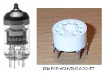
I finished designing the PCB, and the all parts including tube are located
on the one PCB. The tube use B9A PCB mounting socket,
like shown on attached picture, it is also available with goldplated contacts.
The PCBs are already available at the website below, and are of high
quality, like the Aleph PCBs.
Best regards,
Kristijan Kljucaric
http://web.vip.hr/pcb-design.vip
Except tube, the amplifier use pretty much the same components
as original Penultimate Zen 4 from Mr.Pass, and you can use the
components of similar quality and have excellent results.
The Tube Penultimate Zen use one E88CC (ECC88, 6922, 6DJ8, 6N1P)
tube per one channel-monoblock, and here it does make sense to
buy two matched tubes, so you can have even more identical channels.
The E88CC is of high quality, and it even have goldplated pins.
The heat dissipation and the overall size of the Tube Penultimate Zen
amplifier is very like the original Zen-4 of Mr.Pass.
I finished designing the PCB, and the all parts including tube are located
on the one PCB. The tube use B9A PCB mounting socket,
like shown on attached picture, it is also available with goldplated contacts.
The PCBs are already available at the website below, and are of high
quality, like the Aleph PCBs.
Best regards,
Kristijan Kljucaric
http://web.vip.hr/pcb-design.vip
Attachments
kristijan-k said:Hello,
Here is also one example with component values.
Best regards,
Kristijan Kljucaric
http://web.vip.hr/pcb-design.vip
What I am curious about is the power section. Based off the pcb's on your site, you need 3 seperate power supply sections for each amp (assuming mono-blocks). Will you by chance be making a PCB that only uses 1 power supply?
- Status
- This old topic is closed. If you want to reopen this topic, contact a moderator using the "Report Post" button.
- Home
- Amplifiers
- Pass Labs
- Penultimate Zen Hybrid