After being impressed by the sound of my cascoded Baby Zen
( http://www.diyaudio.com/forums/showthread.php?threadid=91012 )
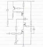
I´ve decided to build a more powerful version of the same circuit.
Before I start spending money I need some questions answered, mostly regarding the choices of mosfets.
1: Is low input capacitance important in the CCS and upper cascode Fets? I guess not, but it would feel good to hear it from someones who actually knows.
2: Can T0-220 dissipate 35-40W continously without compromising expected lifespan? I´m thinking about IRF540/9540 in the CCS/cascode positions.
The reason I want to avoid T0-247 devices is that I want to clamp them all down with a pressure bar and the gain device will definitely be a T0-220 piece (IRF520 or 530).
3: P-channel CCS or N-channel CCS, is one better than the other?
Aleph-type CCS is not of interest here though.
Some design specifications based on the parts I already have:
32V rails from a 2x24V 750VA transformer, if possibly I want to avoid cap multipliers in the PSU and use CLC filters instead.
C-multis would bring the voltage down to 27V or so, and with 3V lost in the cascode I´d only have 24V or so left "to swing with" so to speak.
The absence of cap multipliers means I´l have to give the CCS a slow startup to avoid vicious cone movements when I hit the power switch.
The heatsinks (2 pieces) are good for at least 80-90W a piece
(400 x 70 x 110mm black anodized) so I´m aiming for a quite high bias current, 2,5-3A.
It would be nice to hear some thoughts or reflections before I start putting money into this.
I already know that the topology itself sound really good with crystal clear highs, but now I want to hear it with a little more power than the 2-3W the Babys are capable of.
( http://www.diyaudio.com/forums/showthread.php?threadid=91012 )
I´ve decided to build a more powerful version of the same circuit.
Before I start spending money I need some questions answered, mostly regarding the choices of mosfets.
1: Is low input capacitance important in the CCS and upper cascode Fets? I guess not, but it would feel good to hear it from someones who actually knows.
2: Can T0-220 dissipate 35-40W continously without compromising expected lifespan? I´m thinking about IRF540/9540 in the CCS/cascode positions.
The reason I want to avoid T0-247 devices is that I want to clamp them all down with a pressure bar and the gain device will definitely be a T0-220 piece (IRF520 or 530).
3: P-channel CCS or N-channel CCS, is one better than the other?
Aleph-type CCS is not of interest here though.
Some design specifications based on the parts I already have:
32V rails from a 2x24V 750VA transformer, if possibly I want to avoid cap multipliers in the PSU and use CLC filters instead.
C-multis would bring the voltage down to 27V or so, and with 3V lost in the cascode I´d only have 24V or so left "to swing with" so to speak.
The absence of cap multipliers means I´l have to give the CCS a slow startup to avoid vicious cone movements when I hit the power switch.
The heatsinks (2 pieces) are good for at least 80-90W a piece
(400 x 70 x 110mm black anodized) so I´m aiming for a quite high bias current, 2,5-3A.
It would be nice to hear some thoughts or reflections before I start putting money into this.
I already know that the topology itself sound really good with crystal clear highs, but now I want to hear it with a little more power than the 2-3W the Babys are capable of.
Attachments
So, I did some research.
https://ec.irf.com/ **** IRF, International Rectifier, recommends the following
3 IRF HEXFET TO247AC for Audio.
.
Post #735 - in SEWA Topic, Pass Labs forum:
http://www.diyaudio.com/forums/showthread.php?postid=1070174#post1070174
Another nice & good research
by lineup
At same link, as mentioned in my post,
you can find what P-Channel FET
IRF suggest as most suitable for AUDIO.
(most IRF HEXFET were not made for audio applications,
but as we all know, some of them can be used with fair results!)
lineup
Lineup Audio Lab
Semiconductor Info & Advice

Hmm, I have a bunch of IRFP260N that I got almost for free (compared to what they cost in store), maybe I should give `em a try in the upper cascode and CCS position?
The pressure bar issues can be solved in some way, the gain transistor will only dissipate ~8W so it doesn´t have to be on the main heatsink.
The horrible input capacitance (Ciss >4000pF) won´t be a problem if I decide to use IRFP260N in those positions?
The actual gain transistor will, as mentioned, be a low capacitance device.
Thanks for the info, good to know that IRFP260N is good for something!
Yes, Fuling,
it has got some 4000pF Ciss.
But think like this!
The capacitance would be small, still, in relation to power delivered.
For a smaller FET like IRF610(140pF), IRF9610(170pF) etc. which we often use as Input Transistor,
such a high capacitance would be bad.
Because we do not get much power out of the device.
But for IRFP260N we surely will get VERY MUCH POWER
for this capacitance.
Regarding capacitance, actually using one IRFP260N
may result in lower capacitance OUTPUT stage
than if we need to parallel 2-6 IRFxxx other FET to get same power.
But paralleling means more tricky circuits to make, some resistors maybe,
as well as SOME MATCHING of devices.
I avoid parallel, as much as I can.
For paralleling MOSFET or capacitors
resulting capacitance is adding those capacitances for each device / capacitor.
Paralleling 10 x IRF9610, for example, we get 10 x 170pF ~1700pF.
lineup
There is always more than one aspect of everything, using oversized mosfets with high capacitance would of course be a bad thing but seen from another perspective it might be a good idea to use one big mosfet instead of several smaller.
One IRFP260 equals two or three paralleled IRFP240, both in power and capacitance.
Let´s see what I have in my "secret box":
20+ IRFP260N
50+ IRFP460N
50+ 75645P (T0-220, high power,high current, high capacitance N-channel fet)
+ a few each of IRF9640, 540, 530 and 510.
Budget is an issue in this project (I´ve spent a lot of money on various DIY-projects the last few months...) so it would be nice to use the devices I have, but on the other hand I don´t want to sacrifice performance just to save a few bucks.
for a high power class a
like in your schematic
I would go for IRFP260N, single MOSFET.
I would be lucky if having one or two such MOSFET at home!!!!
As said by IRF homepage, they can be used for AUDIO.
there are more than the capacitance issue
( besides Nelson Pass say high Ciss is not as bad at all,
there are other numbers that are more important,
and he should know,
he has done some extreme many paralleled in some output stages .... )
Paralleling ... well, you know what it takes:
You need Do Some Matching, of those 2-3 FET
You would possible also need some Source resistor in each devices
like 0.10-0.22 Ohm.
Imagine,
if parallel two IRFP260N
with a good current input transistor IRF9610,
working at 100 mA, for example!
This would drive 8000pF with no more problem than usual
in these kind of MOSFET amplifiers.
Two IRFP260N units in parallel ------> Pure Max Power
Regards
lineup
Sommething I can feel...... audio is something i can hear ... what is it for you ...
So then it´s safe to use IRFP260N in my Mini-A,and crank up the current..!!
Sorry for hijacking your thread Fuling.

Ryssen said:
So then it´s safe to use IRFP260N in my Mini-A,and crank up the current..!!
Sorry for hijacking your thread Fuling.
IRFP260N should be almost equal to replace two IRFP240 (or IRFP240N) in parallel.
As this would give in both cases 4000pF input cap.
( 2x2000 = 1x4000 )
IRFP260N would give same operation or better, in my opinion!
As long is operated within SAFE temperature.
And certainly is much less trouble using one device, if we can,
than fiddle with the issues of paralleling.
( some people, like myself, would never parallel - if there is a good option )
Unfortunately I do not know Mini-Aleph circuit.
I know I have seen circuit schematic one time,
but I do not remember how was.
Sorry!
For more exact info, you have to ask somebody who know more
like Nelson Pass
or show me what circuit you will use.
Many Regards
from västerbotten
lineup
--- think it is time I figure out a new signature, soon
I have had that one below for several months now --
...something i can feel
.. maybe groovy bass sounds at max powerRyssen: IRFP260N works perfectly fine in Mini-A, I made a pair of mnoblock for a friend a couple of years ago with those transistors and they played ruler straight all the way up to 200kHz.
Also, I believe Nelson has mentioned that high current, high gm devices are benificial for the bass response.
Lineup: In my first post there is a link to another thread, that a look at the first schematic in that thread but don´t look at the component values.
No transistor in this project will dissipate mor than 35W so there is no need for parallel devices.
Hi Fuling.
Right now I`m working on "similar" single ended class a amp...
I think the issue here is this:
1.Capacitance of the mosfet or any other transistor is reduced when cascoded! How to calculate this reduced capacitance.
2.It is important what would drive the mosfet.
3.Is there any real "sounding" benefit of cascoding in this case?
- Status
- This old topic is closed. If you want to reopen this topic, contact a moderator using the "Report Post" button.
- Home
- Amplifiers
- Pass Labs
- Right mosfet in the right position?