I have built the Zen V2 and was trying to eliminate a hum.
I tried hand winding a choke, and then I used a EI transformer as a choke with the primaries hooked up to a smaller choke. This was very successful until I tried accommodating it in the case of my amp and the interaction between the choke and the main transformer severally reduced the effectiveness of the setup.
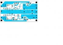
When planning the amp in the first place I had intended to use a capacitance multiplier ala Elliot Sounds project, but in the end I decided chokes were the way to go. When I failed to successfully implement a choke I returned to the capacitance multiplier. As it turns out the regulator described in the Zen V3 is a capacitance multiplier when implemented without the reference Zeners. I had some old MJ2955 transistors lying about so I decided to use these. The two channels are drawing off a single supply and each channel is biased at about 2.6Amps, so peak currents through the multiplier should be at about 7Amps. I started out trying it with just one transistor but it got very hot. I then tried it with two paralleled and they barely get warm. I used a single driver transistor for the pair of them and made no special arrangement to match the main transistors (not even the resistors suggested in the article). They sit on their own heat sink and the base of the driver is referenced to a 4700uF capacitor.
I tried the Multiplier in two different configuration, firstly with a bank of 44,000uF caps before it, and followed by a 10,000uF cap. This produced a very harsh thin sound. I then tried it with the 10,000uF followed by the Multiplier and then the 44,000uF bank. This produced a much fuller sound.
The reason for the difference is given in the article. The Multiplier has a variable impedance at different frequencies with a higher impedance at lower frequencies. This is the opposite of the characteristic of a choke which tends to produce a rich warm sound. The impedance of the second bank works in parallel with the multiplier so the bigger the capacitance the lower the overall impedance at low frequencies. I am almost certain that better transistors will vastly improve this situation.
The hum is still there to a much reduced extent, but I am certain this is a characteristic of grounding arrangement of the first smoothing cap. This is now very difficult to remedy without completely rebuilding the power supply, so I will have to live with it.
My conclusion are;
This is a very satisfactory way of smoothing out hum. Certainly it is cheaper than a comparable choke.
If you intend to do it (which I highly recommend) plan for it from the very start and pay particular attention to the fundamentals of grounding as described in the Elliot sound article.
Invest in some decent transistors with ultra low on resistance, the result is likely to be much more satisfactory and will greatly reduce the cost in capacitors.
There is little problem with heat dissipation so the circuit is easy to accommodate next to valuable capacitors (this is unlikely to be the case with a choke if run at high ampage).
The other great advantage of multiplier is that it doesn't draw down the line voltage in the way that a choke will and so you get more output wattage for your money and less heat.
Shoog
I tried hand winding a choke, and then I used a EI transformer as a choke with the primaries hooked up to a smaller choke. This was very successful until I tried accommodating it in the case of my amp and the interaction between the choke and the main transformer severally reduced the effectiveness of the setup.
When planning the amp in the first place I had intended to use a capacitance multiplier ala Elliot Sounds project, but in the end I decided chokes were the way to go. When I failed to successfully implement a choke I returned to the capacitance multiplier. As it turns out the regulator described in the Zen V3 is a capacitance multiplier when implemented without the reference Zeners. I had some old MJ2955 transistors lying about so I decided to use these. The two channels are drawing off a single supply and each channel is biased at about 2.6Amps, so peak currents through the multiplier should be at about 7Amps. I started out trying it with just one transistor but it got very hot. I then tried it with two paralleled and they barely get warm. I used a single driver transistor for the pair of them and made no special arrangement to match the main transistors (not even the resistors suggested in the article). They sit on their own heat sink and the base of the driver is referenced to a 4700uF capacitor.
I tried the Multiplier in two different configuration, firstly with a bank of 44,000uF caps before it, and followed by a 10,000uF cap. This produced a very harsh thin sound. I then tried it with the 10,000uF followed by the Multiplier and then the 44,000uF bank. This produced a much fuller sound.
The reason for the difference is given in the article. The Multiplier has a variable impedance at different frequencies with a higher impedance at lower frequencies. This is the opposite of the characteristic of a choke which tends to produce a rich warm sound. The impedance of the second bank works in parallel with the multiplier so the bigger the capacitance the lower the overall impedance at low frequencies. I am almost certain that better transistors will vastly improve this situation.
The hum is still there to a much reduced extent, but I am certain this is a characteristic of grounding arrangement of the first smoothing cap. This is now very difficult to remedy without completely rebuilding the power supply, so I will have to live with it.
My conclusion are;
This is a very satisfactory way of smoothing out hum. Certainly it is cheaper than a comparable choke.
If you intend to do it (which I highly recommend) plan for it from the very start and pay particular attention to the fundamentals of grounding as described in the Elliot sound article.
Invest in some decent transistors with ultra low on resistance, the result is likely to be much more satisfactory and will greatly reduce the cost in capacitors.
There is little problem with heat dissipation so the circuit is easy to accommodate next to valuable capacitors (this is unlikely to be the case with a choke if run at high ampage).
The other great advantage of multiplier is that it doesn't draw down the line voltage in the way that a choke will and so you get more output wattage for your money and less heat.
Shoog
Cap Mutiply - Polar Music Prize
Yes, I like Cap multiply.
It is more flexible, and often cheaper solution.
I have also read the Elliot article long ago.
He has learned so many people, so many things,
that he should have our Swedish NobelPrize
Or our "Polar Music Prize"
which has been awarded to
Stevie wonder, Ray Charles, Paul McCartney, Bob Dylan (yes, he showed up!!!), Ravi Shankar ..........
and sveral more prominent music persons.
The prize is founded with money , from ABBA records.
By the Textcomposer/producer Stickan Andersson, who was
the the Owner of Music Producing company POLAR.
ABBA started their thing at his company.
Stickan Andersson is now dead, but
"Polar Music Prize" - the NobelPrize of music,
will live .....................
/halojoy - Proud To Be a Swede
I like the cap multiplier concept too. I was wondering whether to put the 'big' caps before or after the multiplier - after gives a soft start, so I'll probably do it that way. I'm glad to hear you like the sound better that way too.
I plan to use it with a JLH amp I'll be building soon.
I plan to use it with a JLH amp I'll be building soon.
i have just been messing about with my capacitance multiplier.
I have some new observations to pass on.
In Rob Elliots original article he sujests putting a resistor between the main reference cap and ground, this does help to reduce hum a little, but at the cost of sucking out the bottom end.
Splitting the reference capacitance in order to create a second order filter had very little effect on the hum but again sucked out the bottom end.
The resister which feeds the supply voltage to the base of the driver transistor and reference capacitor has a major effect on the sound of the amp. The lower the values the poorer the bass, the higher the values the bigger the bass. I found a value of 1.5K to be satifactory, though I never went any higher.
For the life of me i dont understand the mechanism at work hear so maybe someone would like to explain.
shoog
I built a cap-x psu for my amp but modified the capacitance values (10000uf input, 1000uf for the "fake" cap and 4700uf output). Next to a normal passsive psu i notice MUCH less hum yet no loss of definition or bass. I always felt that the supplied capacitance values were a bit optimistic (they work, but they're less than optimal). I'm more than thankful to Rod Elliot for this great idea!
So your using a Voltage regulator
So your using a voltage regulator chip to create your reference voltage. I used a choke in exactly the same position, but the effect was marginal and so i took it out. I added the multiplier as an afterthought. Its built on a heatsink that float directly above the main torodial so i put down all of the residual hum to dodgy wiring and none ideal location.
Shoog
coffin said:This is my modified one.
The resistor of each emitter are to balance the current run thru each C3519/A1386 BJT.
LM317/337 is good for regulation on C3421/A1358
Coffin,
I noticed you replaced the cap with a voltage regulator. This of course makes it no longer a cap multiplier but a DC emitter follower. Any special reason for this? How did it influence the sound?
Jan Didden
Having the voltage regulator drive an emitter follower is probably a step up from using a Zener, as in ZenV(3 was it?). I would guess that the voltage regulator is a better solution then a Zener, at least when using an emitter follower (as opposed to a source follower).
Geoff Moss has reported better results still by using a current source driving a fixed resistor, then the emitter follower. Audibly superior, he says, although not as big an impact as having separate regulators for each channel.(http://www.gmweb.btinternet.co.uk/jlhupdate.htm)
Of course, using an regulator / emitter follower means you need a bigger heatsink because you would typically have a larger voltage drop across the device(s). You also have to take into account AC line voltage droops, whereas with the simple capacitance multiplier it doesn't care about the absolute voltage.
paulb said:[snip]Of course, using an regulator / emitter follower means you need a bigger heatsink because you would typically have a larger voltage drop across the device(s). You also have to take into account AC line voltage droops, whereas with the simple capacitance multiplier it doesn't care about the absolute voltage.
Indeed, the beauty of the cap multiplier is that you trade regulation for low dropout while keeping the excellent smoothing. As I see it, once you make the step from cap multiplier to emitter follower, its a small step to add some feedback and then you have a regulator. You can even argue that the emitter follower IS a regulator, with local feedback instead of global feedback....
Jan Didden

That sounds interesting
I definately would prefer a more choke like characturistic than the cap multiplier as is definately tends to thin out the bass.
Do you think there are any risks involved in this configeration and do you think it will improve the bass any?
I tried upping the Voltage reference feeding resistor as described in my previous posts. I took it up to 4.7K and the bass was amazingly deep, unfortunately the hum had come back. I put this down to the driver transistor not getting enough current and sucking noise through the resistor. I dropped it back down to 2.35K and this has given a satisfactory improvement in bass but with minimal hum.
I do not understand the mechanism as to why varying the resistance effects the bass response so much, but you will have to take my word for it.
Shoog
I don't think there are any risks vs. the cap multiplier, but you might want to try the circuit out with a dummy load to make it easier to fool around with the capacitor and resistor values. ( I haven't tried such a circuit myself in a power supply, and it may prove to be not such a great idea. ) As to whether it will improve the sound ... I can't speak to that.
I tried that and it seems to work
I tried your modification and it seems to work just as you predicted. means if i stick with it i will have to retune my speakers again. Definately a more choke like characture.
I never thought the power supply would have such a prefound effect on the sound of the amp- I just imagined it would supply clean DC.
Shoog
coffin said:This is my modified one.
The resistor of each emitter are to balance the current run thru each C3519/A1386 BJT.
LM317/337 is good for regulation on C3421/A1358
It's always good practice to put a diode across the emitter collector of C3421/A1358.
- Status
- This old topic is closed. If you want to reopen this topic, contact a moderator using the "Report Post" button.
- Home
- Amplifiers
- Pass Labs
- My experience with a Capacitance Multiplier