wow
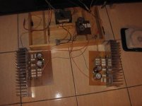
and here it is, worked straight away(phew)....
took it to a local meet yesterday which was a bit of a risk because I hadn't even listened at that point...it held its own in some very esteemed company and got some v.good comments from the valve(I hate ss) guys.
I will post my thoughts after listening over the next few days..
at the moment 3 of the 4 transistors run at 63 degs after 1 hour and 1 of them seems to like it at 72 degs...I'm thinking I might tighten the bolt on that 1 as a first step...the sink runs at a constant 38 degs. With nothing connected at input its inky black into my vofos(see my web site)
Its slightly more sensitive than my EL34 SE but I think already outshines it for exposing detail....early days!!
many thanks to Nelson.
Regards
Ed
Attachments
I've got a bit of a buzz on one channel which is driving me nuts and I wonder if anyone might have a guess at what might be amiss.
It won't measure on the DMM (< 1mv)and it probably wouldnt be visible with less efficient speakers. Its quiet with nothing in the phono, loud when shorted and in the middle when it has a source connected.
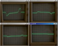
I think I'm looking at PS ripple here but would like some confirmation and any guesses as to why one channel should be louder than the other......the scope is set 1mv at 1ms..measuring output.
Regards
Ed
It won't measure on the DMM (< 1mv)and it probably wouldnt be visible with less efficient speakers. Its quiet with nothing in the phono, loud when shorted and in the middle when it has a source connected.
I think I'm looking at PS ripple here but would like some confirmation and any guesses as to why one channel should be louder than the other......the scope is set 1mv at 1ms..measuring output.
Regards
Ed
Attachments
vitalstates said:I've got a bit of a buzz on one channel which is driving me nuts and I wonder if anyone might have a guess at what might be amiss.
It won't measure on the DMM (< 1mv)and it probably wouldnt be visible with less efficient speakers. Its quiet with nothing in the phono, loud when shorted and in the middle when it has a source connected.
I think I'm looking at PS ripple here but would like some confirmation and any guesses as to why one channel should be louder than the other......the scope is set 1mv at 1ms..measuring output.
Regards
Ed
ground loop
Hi Zen
I've been scratching my head over this....I thought GL as well but can't figure out how.......I checked the cold resistance on the thermistors as I thought that could be the only path....one measured 14.8 ohms and the other 14.4 ohms..I then discounted it at the time cos the voltage across chassis and circuit ground was identical on both channels.
Do you think that might be it??? Do those cl60s normally vary so much??
Ed
Hi Nelson
the transformer was the first thing I played with, rotated about 20 degs each way but it made no difference. All the wires exit directly at the back against the chassis. I even tried a steel sheet between the transformer and the offending board but that didn't help either.
The signal in is about 3/4 inch, the phono is right next to the entry track on the board, I thought that would remove the need for any shielding on the signal wire.
I wish I wasn't such a nerd with hums because it can't be more than 0.5 mv but once I know its there I'm like a bear with a sore head. If, as you say, that trace is definately transformer then I'm going to have to think about a wider chassis I guess.
I'll plod on, and thanks for the advice its much appreciated.
Regards
Ed
yippee
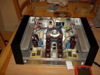
some degree of success getting rid of the buz...with the scope attached I tried various combinations of steel plate between the trannie and the lhs circuit board. Finally got rid of the noise with 3 sheets of 1/16 steel. Will now bolt this in as a permanent fixture as it saves building a wider chassis.
Still find it a bit strange that 1 channel is completely silent...
This mod has certainly sharpened up the stage and I do believe its coping a bit better on more complicated material, although the latter might be due to bedding in...
Regards
Ed
Hi Nelson
referring back to my post #168, the top traces are left and right inputs shorted. These clearly show the difference between left and right circuits. I'm sorry the text bars weren't a bit clearer.
I niavely thought that by shorting the input it gives a true picture of the power supply on the signal circuit, but its likely I need to be corrected here....a little bit of knowledge is a dangerous thing etc etc.....
If there is no difference between the gains of the individual circuits then it clearly shows that my particular torroid is as wayward as can be with its spurious emissions. I ended up twisting it nearly 45 degrees without the slightest change.
Regards
Ed
Since the transformer rotation doesn't affect it and since
shorting the inputs without externally connecting their grounds
together doesn't change it, then it's your wire routing most
likely.
Let's confirm that you're using a "2 star" type ground. This is
where the first star consists of the transformer center tap,
the leads going to the "ground" ends of the power supply
capacitors, and a single fat wire going to the second star.
The second star has a wire going to the first star and then
wires going off to every other signal ground. It also connects
to chassis through a thermistor, and chassis connects directly
to AC earth ground.
The F2 uses dual secondary power supplies that don't share
rails and only share ground through two thermistors in series,
with the chassis connected between the thermistors.
If you are using a single supply, use the same dual star
arrangement, but see to it that the ground leads are cleanly
routed and that the input grounds are connected together
at the input connectors as far away from the transformer
as possible.
I'm sure that if you experiment, you'll find what works.

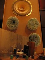
F2 in the background, barely visible but prototype-wise, complete.
Fonkens in the foreground, Marianne Faitfull in between.
I moved the mosfets towards the center of the heat sink and applied grease on the ceramic insulators which improved the heat transfer a lot.
Drilled holes for Speakon connectors and fastened the mains input socket.
My body shivers, tears in my eyes, not sure if The Equipment or ‘la Faitfull’ is responsible, or both...
This is a nice combination, very detailed and sweet sound.
Strange how some gear can reveal information I never heard on well known source material.
‘Why D’ya Do It’ She said…
/Hugo
Attachments
- Home
- Amplifiers
- Pass Labs
- DIY F2 clone