Don´t get too excited, I have no software for drawing schematics so the new ones will also be drawn by hand but I´ll try to make them readable (ist that a word?).
Right now, I´m trying to decide what Mosfets to use in a bigger version of the cascoded Zen, I have a few types to choose between but none of them are optimal. OTOH I´d prefer to use parts that I already have at home...
Right now, I´m trying to decide what Mosfets to use in a bigger version of the cascoded Zen, I have a few types to choose between but none of them are optimal. OTOH I´d prefer to use parts that I already have at home...
You can download a free copy of schematic drafting software from Express PCB. I use it to draft electronic circuits as well as an aid to designing my pcbs.
btw, speaking of pcbs, I'm firing up my newest version of the ZV7-T today. My circuit boards are working perfectly, so far. The only glitch is my power resistors (Q1 and Q2 drain to ground) are getting hot. I can't even begin to touch them. I'm thinking about using the "light bulb" technique to replace the power resistors. I just have to find which wattage gives me 47 ohms.
Here's to hoping you have a wonderful week-end.
John")
btw, speaking of pcbs, I'm firing up my newest version of the ZV7-T today. My circuit boards are working perfectly, so far. The only glitch is my power resistors (Q1 and Q2 drain to ground) are getting hot. I can't even begin to touch them. I'm thinking about using the "light bulb" technique to replace the power resistors. I just have to find which wattage gives me 47 ohms.
Here's to hoping you have a wonderful week-end.
John
Ok, I´ll have a look at the free software whenever I get the time to do it.
Drain to ground, I assume that would be output to ground (I don´t have the schematic in front of me right now)?
If so, I´d use bigger power resistors instead of lightbulbs.
In my world lightbulbs belongs in lamps, not between output and GND in power amps
Drain to ground, I assume that would be output to ground (I don´t have the schematic in front of me right now)?
If so, I´d use bigger power resistors instead of lightbulbs.
In my world lightbulbs belongs in lamps, not between output and GND in power amps

 Now, the heatsink keeps them around 50 degrees C.
Fuling said:I have no software for drawing schematics
so the new ones will also be
drawn by hand .....
.
carpenter said:You can download
a free copy of schematic drafting software
from Express PCB.
I use it to draft electronic circuits
as well as an aid to designing my PCB.
.
thanks, carpenter
www.ExpressPCB.com Download.htm
I decided to try.
I downloaded latest version, May 2006.
It is a good and very easy to use Schematic program.
Two parts:
1. ExpressSCH ... for adding components symbols and wires into a schematic
The Circuit can be exported, Saved, directly to a .BMP image, with different selectable resolutions
or
The Circuit can be Copied to Clipboard and so imported into your Image program.
And from there saved in what format you like: PNG, GIF ....
2. ExpressPCB ... for creating PCB Layout from your circuit
This one I did not test,
because I don't make PCB
.. there are so many members at this forum
that can do this much better .. if we ask them nicely
==========================================
Carpenter,
thanks for the hint about ExpressPCB www.expresspcb.com
Easy and good tool for diyaudio members. (I guess only for Windows users, I have XP Home)
Carpenter,
as a reward you can freely use my circuit I created quickly using this ExpressSCH software.
While I was learning how it works.
( I even did not have to consult the 'Quick Guide' or 'Help documents'! )
 All you others
 Please note and respect that this Attachment below
is for carpenter only!!!!!
lineup
Attachments
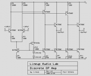
- not to mention balanced in and/or output
- input for driving two power amplifiers in bridge ( one from +out and one from the -out
Most Non-Lineup operational amplifiers
have only one non-inverting output.
1. Resistor in JFET CCS source, should first be adjusted,
to get like 0.6V in that current source feeding two input transistors.
The current in those 1N4148 diodes
determines this voltage across R1 ~ 0.60 Volt.
2. Those other two trimmers (one for CCS in +output, the other for -output stage)
should then be used to achieve balance at the output stages.
We can say this is the Output DC-offset adjustment.
3. Can of course like most Op-Amps be used with single or dual supply.
For single supply, we need input and output caps, of course.
4. Each output stage has got idle Class A!! ~6mA ( 0.6V/100 )
Can for example drive +-4-5mA into 5 kohm= +-20-25 peak ~15 Volt RMS
5. BF245A .. the JFET is only for 30 VDS. So max dual +-15V if using that one.
Use some other JFET, for higher voltage operation.
There are some 40-50 Volt JFET that are easy to find.
For example 2SK170 takes 40 Volt = +-20Volt operation
6. BC550C, BC560C takes 45V, so max +-23 Volt supply for them.
7. By using other types of JFET and BJT small signals
you may tailor your Op-Amp for much higher voltages,
higher currents output
or whatever.
lineup
PS. I hope Fuling decide to download ExpressPCB.
It is a tool what many would need.
Instead of trying to describe circuits with words ... DS.
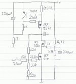
Although the circuit works if built as shown above, I have some suggestions for modifications that probably would improve the performance:
Higher rail voltage. I lost a few volts more than I had expected so I´m running mine on 21,6V, it works but a few more volts would probably be great. 28V would probably be ideal, 3V across the gain transistor and 25V to be shared between the cascode and the CCS.
Higher current. Of course!! I´m limited to 25-30W dissipation per channel by my quite small heatsink, if I could I´d definitely change the 0.56R resistor to 0.47 or even 0.33R
In that case I´d also change the CCS mosfet to something that can take a little more power, like IRF9530 (or -9540 or 9640 or whatever, you get my point).
A trimpot in the voltage divider for the cascode would be nice, I ended up with about 2,8V across the gain Mosfet but perhaps it would be interesting to play around with that voltage a bit?
As far as I can understand the internal capacitances in the Mosfet changes with the voltage, so one or two extra volts to play with could be fun.
I needed quite high input impedance to match the output of my active crossovers, people with good preamps could lower the values of the feedback resistors and probably get improvements here.
Putting the feedback loop outside the coupling caps might also be a good idea, but now we´re getting of the track.
While we´re of the track, why not add an input buffer and an active CCS?
The possibilites are endless, but the amp sounds really good as drawn in the schematic and would probably sound even better with just a little more voltage and current.
As promised, I´ll build a bigger version someday with IRF540/9540 for the cascode/CCS and IRF530 as gain transistor, 28V rails and plenty of current. I got a pair of really huge heatsinks earlier this week and I already have a nice 2x24V 750VA toroid...
Not that I need more amps, but after my first listening I got the impression that the cascoding is a winning concept that deserves proper implementation.
Fuling said:If you guys can´t read this, get thicker glasses!
No problem, dear Fuling.
You make nice schematics with your method.
Your digital camera is not bad.
lineup
AC-län lapplandcarpenter said:lineup, I cut, pasted and saved your last discourse. Thanks; I'll build this amp at a later date when I'm done with my ZV7-T series.
Hey choky, that's a neat set of drafting symbols and will work great with "paint".
Life is great,
John
I tested and tweaked my special op-amp, with both non-inverting and inverting output.
In my MultiSim.
At unity gain +1, buffer, and +15 -15 volt supply.
With input impedance resistor 10k and 10k feedback resistor.
Into 5kohm load.
I got 0.000% THD for input voltage <= +-6.12 V peak input.
At 6.13 V peak input got 0.001% ( -100dB ).
So almost 50% (7.5V) input before my analyzer can see any distortion!
At 1 V RMS input/output,
I get of course no distortion in +OUTPUT, using 10kohm feedback resistor.
But the -OUTPUT (inverted, which has got no direct feedback)
I get
0.102% THD at 1 V RMS input.
And for 2 V RMS this is twice (0.204%) and so on .....
It shows an perfect linear function, where dist is in proportion to output voltage
Besides, this is almost only 2nd harmonics, for the inverting output.
I do not know how to add feedback from both output.
Is there any way, to use for example
two 20k feedback resistors, one from each output?
There has got to be a solution for this,
so both outputs shows 0.000% THD.
Enlighten me, somebody please.
Thank you!
My op-amp circuit is a couple posts up here.
lineup
Fuling said:Thanks guys!
I gave the schematic/PCB software a quick try but I soon realized that it would take a while (for me) to get it going, will investigate it further when I get the time to do it.
I still prefer hand-drawing and scanner...........at least for smaller schmtics..........everything bigger I draw in blocks , and that makes them same
- Status
- This old topic is closed. If you want to reopen this topic, contact a moderator using the "Report Post" button.
- Home
- Amplifiers
- Pass Labs
- Baby Zen for biamping