Grey and/ or John Inlow,
I got the boards yesterday in the mail, thanks John.
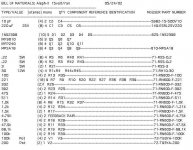
I do have a question. If I pull down the schematic Grey put out on 5/24/02, will the parts on the schem. match the board's screen? I tried to search for a parts list but found none under Aleph X.
Thanks and Merry Christmas,
Vince

I got the boards yesterday in the mail, thanks John.
I do have a question. If I pull down the schematic Grey put out on 5/24/02, will the parts on the schem. match the board's screen? I tried to search for a parts list but found none under Aleph X.
Thanks and Merry Christmas,
Vince

Merry Christmas, fella,
I never got around to posting a formal parts list...or at least I don't remember doing so. Probably should, I guess. Considering that I've got myself involved in the high-powered Aleph-X dingus, I'll have to dredge around and locate the schematic (the version I posted and the prototype had some differences...). If I can keep my focus, I'll get you up a shopping list.
As to what the boards take, I dunno. You'll have to ask the board guys. I'm not sure what path they chose.
Grey
parts list
There's a parts list on the alpha pcb thread that follows Grey's original specs (fairly certain). The latter schematics I posted (same thread) include Grey's follow ups and are not posted in the parts list. If you use the latter schematics you'll need to modify the parts list. The only changes are the two resistors that accompany V2.
John
Bricolo
should we buy the parts for you, too??
A note on the part list: R19-29 should be 20 K max (per Nelson comment) I am using 10K. 68k is too much.
the FDB res can even be 200K and resistor to GND 100 ohms.
5 or 10 pf in the feedback loop should work.
The original IRFP044 should be better here. They have higher transconductance. IRFP140 should work as well.
Yeah, I've been meaning to post a new parts list. There is one posted in the Veta/rev1.0 board thread, although it's for the Beta boards. Parts list for the rev1.0 board is pretty much identical, save for the correction to R19/29. The rev1.0 schematic is just slightly different as well, allowing a bit more flexibility in the connection of the current source to GND or -V.
Unfortunately, I'm on vacation, and relatively poor internet access until I return in January. At that time, I'll post an updated BOM and schematic in .pdf format.
Unfortunately, I'm on vacation, and relatively poor internet access until I return in January. At that time, I'll post an updated BOM and schematic in .pdf format.
Well, I haven't done any simulations or calculations, but from previous experience using mosfets for diff pairs, I know that they have a fairly high input capacitance. What do you get with a high impedance input and a bunch of capacitance? Low-pass filter! I imagine if the input impedance is too high, you'll end up with too much roll-off in the extreme treble, maybe even creeping down into the audible range. Lowering the value of R19/29 reduces the input impedance, since that 68K is effectively in parallel with the other resistors connected to the input node, excluding the 220R (since it looks into a high impedance).
John,
My order arrived in the mail today and the boards look very smart.
Well done mate, you are a champ.
I particularly like the references on the board to Grey Rollins for his credit to the design......where would we be without him!
This should keep me busy for quite a while, the journey continues.
Cheers
Ian
- Status
- This old topic is closed. If you want to reopen this topic, contact a moderator using the "Report Post" button.
- Home
- Amplifiers
- Pass Labs
- Aleph-X parts list
