(not much to do with the 750..but...)
what we want, more than anything, is a regulation stage of some sort that is completely passive, thus removing the effects of transistor noise and transient modulation in the PS rail, if properly done. Only then will you hear properly done transients, for the first time in your life. You might find it a bit screechy, as we have become accustomed to greyness, haze, etc, as an excuse for a complex transient chracteristic. I expect the opposite might be true, in some cases, as like when a superior capacitor is used, the HF drops in 'noticability' as time based smear is cleared up. (signal x time= db level, to the human ear-in the microtransient sense) it does not matter the level of regulation that the given regulator is speced at, it's the fact that the signal does bounce around on that power rail regardless of what regulator is used. That lously 0.01% or better of PS modulation (after regulation) IS the entire issue. Part of the proof of that, is that these 0 to lightspeed highly regulated-(1 billion regulators) zillion dollar pre-amps out there, still sound like total hazy irritating shite.
A leveraged system of some sort, that uses the odd zener, tied to a secondary current replenishment stage. Keep the whole thing at lightspeed, by having zero active components in the thing, except for the zeners. Maybe no zeners. Maybe bury the zeners, under inductors. As for active..damn transistor feedback stuff. bad for good tunage.
I've got something stirring in the back of my brain on this one. It will pop out when it wants to. Anyone care to point to such, if it is around now, and I'm just behind the times? I need something to stare at to make the muse work.
Chris:
It would sort of be the polar opposite of the circuit I showed you (when I was at your place ) that seems to be 'dynamically phase shifting' micro transients according to the circuit load. That one works, so this might work as well. I just gotta figure it out. 90% of the information required to figure that one out is missing in this conversation, so it would be tough stumble onto it.
What I am talking about here, is to use the zener or similar, possibly high resistance, under the inductor -going to ground, but have the inductor as mass stabilizaton in a paralell line with the PS rail. Seems stupid as driving nails with wet spagetti on first take, but some combination thereof , all passive. It's slowly coming clear.
Newman used the collapsing field established in an open ended inductor circuit for his experiments and patents *, and similar may work here, for rail stabilization. It might be possible to use it in conjunction with active regulation, to fix that small problem with recovery in the active circuit of the regulator, ie the feeback time constants. The inductor would excell in such use, properly attache to the circuit, of course. The usual place for an inductor is series, but in this case an use, it would be more like a parallel reluctant capacitor. I'm sure folks would think this is stupid as the day is long, but I say, "hey, not so fast". Inductors have mass (storage) considerations involving time, so they may be of use, properly employed. Capacitors obviously work, and would need to be there for buffering the normal aspects, but a properly applied inductor might beat out a capacitor, when it comes to micro transient current issues. Purveyors of tubes are fond of their choke supplies for a reason.
Remember what happens when a capacitor sits with it's ground not coupled, in circuit. Put an inductor there, and think it through. Then keep going.
* What Newman would do, is use huge inductors, 900lbs or more. He would connect the charge circuit,and then disconnet in so sshort a time that the circuit would only organize the electrons, but not actually pass current. Just before the electons were all lines up and ready to pass current....he'd disconnect the charge circuit, the field would collapse, and before it collapsed, he'd switch to connecting a circuit for capturing that energy. Few people realize that the electrons on the pathway must organize into a cohesive and aligned state along the entire wire,as a cohesive whole, before current conducts. Voltage leading the current field....as the organizational pathway zips up the wire until the organization is complete (reaches the other end - it takes TIME - it's a mini tsunami running for the other end of the wire), then current fields are established and current is conducted. This little tidbit is important. The field is established in the open ended conductor, and has mass via modulation. The right sized inductor, that is complementary to the feedback speed recovery issue of the regulator circuit. Yeah, that might work.
It would sort of be the polar opposite of the circuit I showed you (when I was at your place
) that seems to be 'dynamically phase shifting' micro transients according to the circuit load. That one works, so this might work as well. I just gotta figure it out. 90% of the information required to figure that one out is missing in this conversation, so it would be tough stumble onto it.What I am talking about here, is to use the zener or similar, possibly high resistance, under the inductor -going to ground, but have the inductor as mass stabilizaton in a paralell line with the PS rail. Seems stupid as driving nails with wet spagetti on first take, but some combination thereof , all passive. It's slowly coming clear.
Newman used the collapsing field established in an open ended inductor circuit for his experiments and patents *, and similar may work here, for rail stabilization. It might be possible to use it in conjunction with active regulation, to fix that small problem with recovery in the active circuit of the regulator, ie the feeback time constants. The inductor would excell in such use, properly attache to the circuit, of course. The usual place for an inductor is series, but in this case an use, it would be more like a parallel reluctant capacitor. I'm sure folks would think this is stupid as the day is long, but I say, "hey, not so fast". Inductors have mass (storage) considerations involving time, so they may be of use, properly employed. Capacitors obviously work, and would need to be there for buffering the normal aspects, but a properly applied inductor might beat out a capacitor, when it comes to micro transient current issues. Purveyors of tubes are fond of their choke supplies for a reason.
Remember what happens when a capacitor sits with it's ground not coupled, in circuit. Put an inductor there, and think it through. Then keep going.
* What Newman would do, is use huge inductors, 900lbs or more. He would connect the charge circuit,and then disconnet in so sshort a time that the circuit would only organize the electrons, but not actually pass current. Just before the electons were all lines up and ready to pass current....he'd disconnect the charge circuit, the field would collapse, and before it collapsed, he'd switch to connecting a circuit for capturing that energy. Few people realize that the electrons on the pathway must organize into a cohesive and aligned state along the entire wire,as a cohesive whole, before current conducts. Voltage leading the current field....as the organizational pathway zips up the wire until the organization is complete (reaches the other end - it takes TIME - it's a mini tsunami running for the other end of the wire), then current fields are established and current is conducted. This little tidbit is important. The field is established in the open ended conductor, and has mass via modulation. The right sized inductor, that is complementary to the feedback speed recovery issue of the regulator circuit. Yeah, that might work.

This way, you can have over-unity technology in your preamp.  Sort of. You'd be using the opposite of the known effect of capacitors being left open ended in a circuit, but the inductive version. Capacitors would cause issues. This might fix them.
Somebody make this, so I don't have to. I've got plenty of other things on my plate. Please don't try to charge me a fortune either. I hate that. I know, I know, I'm getting itchy right now, thinking of an inductor hanging off a circuit like that, all connected to nothing. It's crazy, maybe. But maybe crazy like a fox.
And perhaps that's part of the secret behind Peter Belt's doings. I don't think he had any idea why it worked, as subtle as it was. This may be why. Use a big enough inductor, and you'll likely have something. Whatever the result, it will be very telling. Negative, or positive result, both will be very educating.
The field is established in the open ended conductor, and has mass/field considertions strictly via the micro-modulation in the paralell PS rail. The right sized inductor, that is complementary to the feedback speed recovery issue of the regulator circuit. Yeah, that might work.
So an open ended inductor sticking off a circuit, right at the point where the PS enters the circuit. Something in the H range, maybe. Maybe even a open (ungrounded) cap on it's backside as a secondary experiment. That could prove interesting. A very interestng resonant circuit, bastardized into microstabilization of PS rails. I think it would prove most intersting in a tube circuit PS. Just a guess. The RF guys would know best on this one, it equates out to be something similar to a RF antenna circuit. Except we would be shoehorning it into different service.
Ah, yeah never know.
Sort of. You'd be using the opposite of the known effect of capacitors being left open ended in a circuit, but the inductive version. Capacitors would cause issues. This might fix them.Somebody make this, so I don't have to. I've got plenty of other things on my plate. Please don't try to charge me a fortune either. I hate that.
I know, I know, I'm getting itchy right now, thinking of an inductor hanging off a circuit like that, all connected to nothing. It's crazy, maybe. But maybe crazy like a fox.And perhaps that's part of the secret behind Peter Belt's doings. I don't think he had any idea why it worked, as subtle as it was. This may be why. Use a big enough inductor, and you'll likely have something. Whatever the result, it will be very telling. Negative, or positive result, both will be very educating.
The field is established in the open ended conductor, and has mass/field considertions strictly via the micro-modulation in the paralell PS rail. The right sized inductor, that is complementary to the feedback speed recovery issue of the regulator circuit. Yeah, that might work.
So an open ended inductor sticking off a circuit, right at the point where the PS enters the circuit. Something in the H range, maybe. Maybe even a open (ungrounded) cap on it's backside as a secondary experiment. That could prove interesting. A very interestng resonant circuit, bastardized into microstabilization of PS rails. I think it would prove most intersting in a tube circuit PS. Just a guess. The RF guys would know best on this one, it equates out to be something similar to a RF antenna circuit. Except we would be shoehorning it into different service.
Ah, yeah never know.
It looks interesting, and potentially useful, but the whole idea is to stay way from the time issues of the transistor and transistor noise if possible. If you guys can use it, then use it, and use it well. Inductors in active circuits in the way you have proposed may work incredibly well too. Maybe better. Who knows.
In all seriousness, the large majority of you guys will know far better than I. I have spent little energy on circuit design, and know little about it. I couldn't design an active circuit if you put a gun to my head and seiously threatend to kill me.
I will literally visualize the flow of energy in the circuit drawing and figure out if it is useful or not.
What I have spent all my energy on, is the minutae of materials science, at the subatomic or atomic level. Wave/particle,and it's applicaction in audio, in this case. Nature of reality, etc. No schooling, just a good feel for it, and a lack of fear for making myself look like an idiot. seems to work. I chase after fundamentals, that's where I get my kicks, as it turns out to be universal keys, instead of complex and never ending rule books. That way, the basics to everything can be put on a single page, for example.
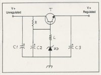
Take the supplied schematic, and add an inductor on the output. As a designation, put xH (Henries, not millihenries) beside it. Leave the normally ground (or whatever) lead, specifically attached to NOTHING. The inductance is gradual through the inductor's wire length not instantaneous, so the thing will have an effect like a capacitor, but expressed in near light speed reluctance. Reluctance to allow the field to alter. Ie, mass reluctance. An inductor, behaving like an inductor, but specifically only at near lightspeed. Which is the whole point. Very RF...which pretty well equates to the time cosntant issues of feedback in a PS regulation circuit, or standard feeback in circuits in general, for that matter. a very bizzare regulator, designed to ONLY deal with micro changes at extreme speeds or rates of change. Inductors store energy...as we all know. Ones attached to nothing, are still full of and storing energy. Meaning, their reluctance to change, of any sort is still and always operative. As stated, the high speed micro-modulation in the PS rail, causes the inductor to react, by imposing it's will on the rail. Which is to disallow change.
This effect can obviously be utilized eleswhere. This whole thing may turn out to be wasted space, but hey, why not take a look see.
In all seriousness, the large majority of you guys will know far better than I. I have spent little energy on circuit design, and know little about it. I couldn't design an active circuit if you put a gun to my head and seiously threatend to kill me.
I will literally visualize the flow of energy in the circuit drawing and figure out if it is useful or not.
What I have spent all my energy on, is the minutae of materials science, at the subatomic or atomic level. Wave/particle,and it's applicaction in audio, in this case. Nature of reality, etc. No schooling, just a good feel for it, and a lack of fear for making myself look like an idiot. seems to work.
I chase after fundamentals, that's where I get my kicks, as it turns out to be universal keys, instead of complex and never ending rule books. That way, the basics to everything can be put on a single page, for example.Take the supplied schematic, and add an inductor on the output. As a designation, put xH (Henries, not millihenries) beside it. Leave the normally ground (or whatever) lead, specifically attached to NOTHING. The inductance is gradual through the inductor's wire length not instantaneous, so the thing will have an effect like a capacitor, but expressed in near light speed reluctance. Reluctance to allow the field to alter. Ie, mass reluctance. An inductor, behaving like an inductor, but specifically only at near lightspeed. Which is the whole point. Very RF...which pretty well equates to the time cosntant issues of feedback in a PS regulation circuit, or standard feeback in circuits in general, for that matter. a very bizzare regulator, designed to ONLY deal with micro changes at extreme speeds or rates of change. Inductors store energy...as we all know. Ones attached to nothing, are still full of and storing energy. Meaning, their reluctance to change, of any sort is still and always operative. As stated, the high speed micro-modulation in the PS rail, causes the inductor to react, by imposing it's will on the rail. Which is to disallow change.
This effect can obviously be utilized eleswhere. This whole thing may turn out to be wasted space, but hey, why not take a look see.

It's very easy to figure out if I'm screwed in the head or not. Dig through your stuff for a pair of identical H sized small signal inductors, and solder one end of them on the PS rails of your preamp or the like, and listen.
Takes about 15 minutes.
Then you'll know.
Whatever the result, it should be interesting.
Takes about 15 minutes.
Then you'll know.
Whatever the result, it should be interesting.
Putting the two inductors hanging off on the PS rails of my counterpoint 3.1 preamp's line section... I feel like an idiot. Like the first guy who ever ate an oyster.
I used a pair of 0.5watt 10mh inductors. The first two I came arcoss.
But it seems to be doing something. Only time will tell, and maybe a handful of measurements wouldn't hurt either. I apologize, I generally don't do measurements (unless I'm working on speakers), you guys will have to do that part, if you think the whole thing has merit.
~~~~~~~~~~
Either I'm hearing clean transients..or I'm hearing time based smear. One of the two.
Yep. There's now an entire realm of subtle HF I've never really heard that way before. Or I'm messed up in the head.
Very interesting.
More testing, definitely. If it does turn out to be a workable thing, one would likely have to match the inductor characteristics to the level of basic fluctuation within the PS, on all levels.
Edit. Yes. I think that things are definitely..'faster'.
The closest thing to totally quiet (infinately quiet?) is batteries. Good ol' lead acid deep cycle marine batteries are best, unless you have access to laboratory grade, voltage reference batteries.
Then the only pop corn noise (zero crossing transients) might come from the linearly regulated solar cells charging your battery set.
(I thought you Canadians 'way up north knew all about living off the grid??)

Then the only pop corn noise (zero crossing transients) might come from the linearly regulated solar cells charging your battery set.
(I thought you Canadians 'way up north knew all about living off the grid??)
I do have about 4000 watts worth of cells, I've been saving..and I wanted to make a high current set of solar powered monoblocks. Solar powered 300 WPC monoblocks.
So..the inductors, are definitely doing SOMETHING. Exactly what, is the question.
Are we following the Gourd, or are we following the Shoe?
~~~~~~~~
Edit:
I am now convinced.
It works, IMHO.
For tube circuits, with their large field considerations, it's a match made in heaven.
So..the inductors, are definitely doing SOMETHING. Exactly what, is the question.
Are we following the Gourd, or are we following the Shoe?
~~~~~~~~
Edit:
I am now convinced.
It works, IMHO.
For tube circuits, with their large field considerations, it's a match made in heaven.
" ... So.. the inductors, are definitely doing SOMETHING. Exactly what, is the question. ..."
Exactly! When guitars were first amplified, it was discovered that winding the pickups with wires running in opposite directions produced "hum bucking" pickups ... thus musicians have known through trial and error, what amateur radio builders since Tesla have known = resistors restrick the flow and capacitors store the flow ... and coils buck the ocsilating flow trend.
The hydraulic model works for understanding capacitors and resistors, but you have to go to Maxwell & Tesla to really understand inductive coils. Induction works on the "leading edge" of the rising potentials, capacitance works on the "trailing edge" of falling potentials.
A combination of capacitors and inductors can be made such that the net effect is "zero" spikes or noise for a specific frequency or band of frequencies ... but not for all frequencies or all noise.
As a matter of practicality, common laboratory grade power line filter (series / parallel C - L - C - L tanks) may be be applied to DC power rails with very good results.
(Show me your diagrams / schmitics and I'll dig up some of mine.)
"All the world's problems can be fixed by resolving the impedence mis-match ..." - Robert Porter / Mad Science.
What I think is going on here, in a tube circuit, with the higher potentials, thus larger fields in the inductors..which are convertable to mass on collapse..... is that the attempt of the rail to fluctuate, is causing the established field in the inductor and surrounding air, to collapse into current, which is injected into the rail, thus disallowing it to sag. But only at near light speed. ie, propogation speed in the wire. Thus, fixing the last remaining issue in a regulated rail...the feedback time constants. however, one does not need regulated rails to benefit. My Counterpoint preamp (current unit that is in use, I have way too many preamps) does not have regulated rails, but it is definitely doing some very good things for it.
Hard to draw a circuit where a inductor is attached to almost nothing.
Instructions:
1) Attach lead A to PS rail.
The end.
Hard to draw a circuit where a inductor is attached to almost nothing.
Instructions:
1) Attach lead A to PS rail.
The end.
" ... [Its] Hard to draw a circuit where a inductor is attached to almost nothing ..."
PS rail ------/\/\/\/\-----
...............A...........B
If A is attached to a DC source (with some noise) then the inductor would distort the noise component, turning it into heat and magnetic flux ... with the possibility, depending on the coil type and its self resonance frequency, of "broadcasting" a portion of the noise into the air (ether?) at B, although the exact source would depend on how long the lead at B is and the diameter of the coil.

"Anything worth doing is worth doing for money ..." - Alfred E. Newman / Mad Magazine
(I wish we could use null spaces in this text editor instead of dots ...)
PS rail ------/\/\/\/\-----
...............A...........B
If A is attached to a DC source (with some noise) then the inductor would distort the noise component, turning it into heat and magnetic flux ... with the possibility, depending on the coil type and its self resonance frequency, of "broadcasting" a portion of the noise into the air (ether?) at B, although the exact source would depend on how long the lead at B is and the diameter of the coil.
"Anything worth doing is worth doing for money ..." - Alfred E. Newman / Mad Magazine
(I wish we could use null spaces in this text editor instead of dots ...)
Well, who else has tried this? An aspect that may come into play, is the impedence of the wire of the given inductor vs that of the impedance of the trace or wire of the PS rail it is attached to. For maxiumum effect, and to avoid lightspeed 'impedence shearing' (think fluid flow dynamics, it kinda works in that particular aspect) of the inductor FROM the circuit it is trying to affect (impose it's will on) at the moment of change (high delta), the inductor must have a low enough DC resistance. So, in the final analysis, the inductor must match the PS issue and pathway on both AC and DC impedence analysis. Thus, two inductors of differing design and wattage rating (resistance, wire diameter, core type and physical aspects, etc) but identical value (H), might create a situation that sounds completely different. Thus the need for 'tuning', at least at first. Until the ramifications are understood.
Make sense? I'm just throwing that out there, but it seems to make sense - on the surface. (a maxwellian pun)
Get thee to radio shack, and buy a few of those el-cheapo inductor packs.
Make sense? I'm just throwing that out there, but it seems to make sense - on the surface. (a maxwellian pun)
Get thee to radio shack, and buy a few of those el-cheapo inductor packs.
Hi Ken,
We have to go to "The Source". Has a foreboding sound to it, doesn't it?
Now correct me if I'm wrong, but an inductor operates on a change of current through it, does it not? This may have an effect at RF frequencies but I can't figure out what can happen within the audio passband.
-Chris
They don't exist in Canada anymore.Get thee to radio shack
We have to go to "The Source". Has a foreboding sound to it, doesn't it?
Now correct me if I'm wrong, but an inductor operates on a change of current through it, does it not? This may have an effect at RF frequencies but I can't figure out what can happen within the audio passband.
-Chris
One way to state it, is that an inductor resists any changes in the field or 'matrix of energy' that is established throughout it's physical space that it occupies, and the immediate area surrounding it.
Added to that, is the field has a mass characteristic, like a tightly wound spiral, in terms of the wire itself. At the propogational speed of voltage (approximately 80%+ of lightspeed) along the wire pathway, it's kinda like an infinity ended energized spring. It is this aspect of the interaction of the voltage propogation vs the current field that we tend to like to call 'inductance'. There is no curent field aspect, in the traditional sense, until that "mini-tsunami of 80% light speed leading voltage", completes it's journey to the other end of the wire and connects to the rest of the circuit..THEN current conducts. The old first semester part of voltage leading current in inductive circuits.
It's like that in all circuits. This is the time delay and transient smearing chracteristics of a feedback based regulation circuit. Which is exactly why many folks find - that massive feedback coupled circuits sound quite harsh. The horse (distortion leading edge) actually leaves the barn, before the feedback circuit can correct the rest of the distortion. Thus, the ideal of gentle levels of local feedback, to cut this issue to a degree.
(Sidenote: This is the exact issue that states a clear as can be, that in acoustics, active feedback control circuits simply don't work for music signals, due to the very low speed of sound in air. Yet entire companies exist that get people to swalow their marketing hyperbola, and buy their junk, and try to call it music. Be it known, I'm not afraid to say the active acoustics correction phenomena going around these days in audiophile circles, is definitely an emperor without clothes. I know that it sounds like harsh condemnation, but it is a sad thing, mostly. The whole thing only works a short distances, and at sub frequencies. Basically, the original premise of active acoustical noise control was to deal with steady state signals, like motors, which have exactly repetitive signals. Active control, be it feedback or feed-forward works for acoustical 'noise' control. Sort of. The signal must be exactly repetitive and cyclic and low frequency, and the distances must be small between the corrective and offending emissive device. Music signals -which do not repeat themselves- will simply not respond well to such systems.)
This is that exact propogation issue, applied to what an open ended inductor looks like on the 'electrical fundamentals analysis', to correct that last remaining issue, when feedback based regulators are used in PS rail circuits. The effect, properly applied, may be interesting enough, that it works well for tube circuits, which have enormous voltage fields, and low current.
Inductors store energy. A field is always in them. In the case of a tube circuit, for example, the voltage field is enormous.
One way to look at it is the voltage field x current density = energy. In a tube circuit, the open ended inductor attached to the PS rail is definitely part of the large voltage field. Thus, it has a signifigant amount of energy it can convert to current, when it is pressed to 'change', by the PS rail, which is attempting to fluctuate. The inductor, on the propogational voltage speed level, or that near-lightspeed propogational rate-throughout the actual length of the winding of wire, will convert the voltage field to a injection of current into the rail, thus preventing it from sagging. Good ole' inductive collapse, the thing that destroys switches and relays in inductive circuits.
Only at the super fast propogational rate of 80% of lightspeed, does the open ended inductor actually operate as this freaky regulation circuit. At any lower rate of change (lower hz) of voltage in the PS rail, the inductor ceases to function as a 'powered circuit' or 'regulator'.
Make sense?
Essentially, what you are doing, is using an inductor as a 'high speed only' capacitor in a PS rail support scenario, an inductor that is faster than any capacitor, for this specific type of application. You are utilizing the leading voltage field aspect, not the lagging current aspect.
The backside of this, is a spray of RF off of the inductor - in the frequencies involved. You cannot shield or ground the inductor, otherwise the effect of utilizing the leading voltage field is cancelled out.
Make sense?
Other than the odd sentence here and there, not to me, no.
- Status
- This old topic is closed. If you want to reopen this topic, contact a moderator using the "Report Post" button.
- Home
- Amplifiers
- Pass Labs
- Power supply idea