Hi guys,
I've searched for a concise, consolidated thread of information -- most of what I seek is scattered like precious gold flecks in a creek-bed.
I'm hoping that the brains in our group can use this thread to explain to the budding amateur FET users in this forum how to properly use the MOSFET. How are they similar or different from the bipolar transistor? What formulas can be interchanged, or used when modified?
Examples and associated formula would be most welcome. These examples should be well written and all mathematical procedure laid out. Use and explanations of Ohm's law are paramount.
Then there are the practical "tricks-of-the-trade" -- what rules must be followed to avoid disaster.
What do you think; is this a viable project? Could it be a "permanent" thread?
Don't be shy...
all the best,
John")
I've searched for a concise, consolidated thread of information -- most of what I seek is scattered like precious gold flecks in a creek-bed.
I'm hoping that the brains in our group can use this thread to explain to the budding amateur FET users in this forum how to properly use the MOSFET. How are they similar or different from the bipolar transistor? What formulas can be interchanged, or used when modified?
Examples and associated formula would be most welcome. These examples should be well written and all mathematical procedure laid out. Use and explanations of Ohm's law are paramount.
Then there are the practical "tricks-of-the-trade" -- what rules must be followed to avoid disaster.
What do you think; is this a viable project? Could it be a "permanent" thread?
Don't be shy...
all the best,
John
MOSFET BRAIN STORM
hi
good idea, carpenter
sure there is knowledge in this forum at absolute highest level
even compared to anywhere else in this world ... !!!
now one thing,
why don't you throw in a practical example of something you have in mind
some kind of amplifier like design
stupid or crazy or more sensible does not matter
because by and by the brainstorming of clever MOSFET posters
will slowly bend your MOSFET creation into something nice
while we go along
who knows
might be one of those everlasting projects topics
that already are among those
www.diyaudio.com Pass Labs forum Classicals
What you say, my friend?
Isn't this a good idea, say?
lineup
a long time member
with several 1.000 posts here around,
even though a long pause was forced upon me
for some reason
Your idea is fine...
... and I do read your many posts with avid interest.
What I was hoping for was our own version of "PRACTICAL MOSFET SOLID-STATE CIRCUIT DESIGN".
For example: take a single FET and add a voltage divider bias network, then add drain and source resistance. With great care, explain how the voltage and amperage is calculated from known values -- or how to find an unknown. Also, show how to calculate the necessary resistance to set an operating point. Explain the various operating points.
This can be short, sweet and concise.
It could also be a bit like N.P.s Zen articles, but without a specific end product, just the concepts -- well explained concepts.
Basically, I would like to see us design our own handbook that looks and smells like a bipolar transistor handbook, but with MOSFETs and JFETs in mind.
The really neat thing? Any one of us could design anything because the knowledge base is all located in one place. No more skimming and extrapolating N.P.s zen articles, or our hastily scribbled notes. No more wondering where that beautiful little tid-bit of information is located at DIY Audio...
If this were done properly, I can see this becoming the reference base the DIY world craves.
I'd also like to discover a way for us to create donations to assist DIY Audio. Maybe a publication?
This is such a cool forum, I'd like to see it continue to grow and have even more features to benefit the members.
John
for jfets, some good material has already been prepared by an expert:
part 1 is here: http://www.borbelyaudio.com/adobe/ae599bor.pdf
part 2 is here: http://www.borbelyaudio.com/adobe/ae699bor.pdf
mlloyd1
part 1 is here: http://www.borbelyaudio.com/adobe/ae599bor.pdf
part 2 is here: http://www.borbelyaudio.com/adobe/ae699bor.pdf
mlloyd1
It's not really a complex subject, and if you go back and
read my articles starting with the Mosfet Citation 12, you'll
see most of the issues covered in the little tutorial ghettos
embedded in the articles, at least for Mosfets and power
JFETs, and you can add those to Borbely's comments.
www.passdiy.com
read my articles starting with the Mosfet Citation 12, you'll
see most of the issues covered in the little tutorial ghettos
embedded in the articles, at least for Mosfets and power
JFETs, and you can add those to Borbely's comments.
www.passdiy.com
Re: Your idea is fine...
My suggested idea in my first post,
was that
you throw in a practical, maybe beginners like stupid, real world design example..
Why did I suggest this?
Yes, I know from experience from this and other forums,
that such a general request for theoretical stuff, formulas and good guiding rules
won't attract posters at all.
Most people are not too much bothered with abstract formulas.
They want some real stuff to relate to.
And so eventually get interested and post some good stuff.
For your very good idea to be a success, it is my 100% opinion,
you would need to supply something to get people going.
carpenter, I think your idea is super!!
This is why I do not want it to die.
So, I give my best advice to try get good activity in this thread.
lineup is certainly not like most people .. but maybe knows what will activate average diyaudio members to post
http://lineup.awardspace.com/
carpenter said:
What I was hoping for was our own version of
"PRACTICAL MOSFET SOLID-STATE CIRCUIT DESIGN".
-------------
It could also be a bit like N.P.s Zen articles, but without a specific end product, just the concepts -- well explained concepts.
Basically, I would like to see us design our own handbook that looks and smells like a bipolar transistor handbook, but with MOSFETs and JFETs in mind.
-------------
If this were done properly, I can see this becoming the reference base the DIY world craves.
My suggested idea in my first post,
was that
you throw in a practical, maybe beginners like stupid, real world design example..
Why did I suggest this?
Yes, I know from experience from this and other forums,
that such a general request for theoretical stuff, formulas and good guiding rules
won't attract posters at all.
Most people are not too much bothered with abstract formulas.
They want some real stuff to relate to.
And so eventually get interested and post some good stuff.
For your very good idea to be a success, it is my 100% opinion,
you would need to supply something to get people going.
Could be:
.. a SCHEMATIC of a horribly bad MOSFET circuit - for people to get upset from and so correct you
.. an IMAGE of a lonely MOSFET TO247 N Channel, waiting for some circuit suggestions
.. a LAYOUT of PCB circuit board, with one input resistor to a MOSFET GATE + 2 DRAIN, SOURCE resistors to set Idle Current and Gain
.. a List of DESIGN GOAL SPECIFICATIONS for a power amplifier:
* Two IRF240 / IRFP240 for output stage
* Drive my 4 Ohm speakers
* Minimum 10 Watt output
* Class A
* Input impedance >= 10 kohm
* Simple circuit
* Basic protection function to avoid damage my Speakers
.
carpenter, I think your idea is super!!
This is why I do not want it to die.
So, I give my best advice to try get good activity in this thread.
lineup
is certainly not like most people .. but maybe knows what will activate average diyaudio members to posthttp://lineup.awardspace.com/
Thanks everyone,
Nelson, I appreciate being turned on to the "Citation 12" article. In fact, I'd forgotten about the "legacy projects". I'm going to reread all of them.
I'm fascinated by the bipolar publications I've been devouring. I'm hoping the MOSFET isn't any more difficult to calculate for than the bipolar.
mlloyd1, thanks for the lead on the Borbely articles.
Hey lineup, you're terrific. I appreciate your enthusiasm more than you can imagine. Perhaps it would be useful to dissect very simple, popular amplifiers and explain the math that went into their resistor values. Nelson does a wonderful job of suggesting what values to use, but I'm sometimes at a loss with his reasoning; this is NOT his fault, just my ignorance. I'm improving, but its taken years; mostly because this is a hobby , not a necessity. Also, there's a thing called "raw talent". I'm a much better carpenter than an electronics major.
At least this thread has offered some reading samples for everyone interested. Perhaps more links can be added as time goes on.
Once again, thanks everyone,
John
Mosfet for VAS
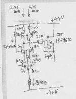
I have a strange problem. I use mosfet (IRF9610) for VAS. The schematic is like below.
The differential is Jfet, K30GR. Each is biased about 2.75mA. The differential is cascoded about 25V by Q3-Q4.
The load is current mirror of Q5-Q6.
This differential is driving VAS mosfet Q7=IRF9610 without source degeneration. Q7 has 220ohm base stopper and 20pF miller cap to advoid local oscilation.
The sound of this is not normal (bad). Later I read in here MikeB wrote that if the configuration is like this (differential has current mirror load on top, and driving mosfet VAS), the gain is infinite at DC, since at DC mosfet don't draw any current, while current mirror is high impedance output (collector-collector).
The sound is like have very much intermodulation.
Later I tried to load the VAS drain with R to ground, not much help.
A help comes when I put R1 (// with miller cap). The value is 220k. The sound is getting better (but not like what I expected).
1. What is happening here?
2. Is Mosfet suitable for VAS? Mosfet has big capacitance, while it always have +/-voltage swing (internal cap varies badly) in the VAS position, VDS varies badly without cascoding. I've seen some commercial amps with mosfet VAS without cascoding, how can they do that?
3. If it is suitable, is it bad if the differential has current mirror load for driving mosfet VAS? Do I need a buffer before mosfet VAS gate or something else?
Attachments
Hi, Mr. Pass,
The IRF9610 that I use in VAS (common source) appears to be from IRF. You have mentioned about the "flaw" of P mosfets from IRF in several posts, and also in mos.pdf. Charles Hansen also found out about this.
Is the strange sound I hear from the configuration in post #8, could it be because I use Pmosfet from IRF in common source configuration?
Maybe it is not the schematic that is wrong (driving mosfet VAS from input differential pair+current mirror load)?
Like always, it's very late for me to understand what NP wrote
He already wrote this long-long time ago, I found out the importance just recently.
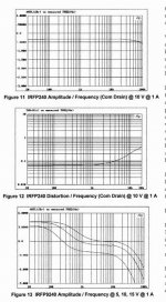
In fig 11 there is a graph of amplitude/frequency for of IRF240. It is quite flat.
In fig 13 there is the same graph for IRF9240 (P channel) from IRF device. This graph is not good, I think, not linear, even in the audio spectrum.
If we compare fig 11 and 13, there must be something wrong with IRF P channel that could not be fixed from outside (elsewhere in the cct).
The question is : how audible is the "imperfection" this IRF P channel? Is it audible (especially in VAS position = common source), or it is not audible (only appears on measurement equipment)?
Charles Hansen also wrote about this IRF P channel :
He already wrote this long-long time ago, I found out the importance just recently.
In fig 11 there is a graph of amplitude/frequency for of IRF240. It is quite flat.
In fig 13 there is the same graph for IRF9240 (P channel) from IRF device. This graph is not good, I think, not linear, even in the audio spectrum.
If we compare fig 11 and 13, there must be something wrong with IRF P channel that could not be fixed from outside (elsewhere in the cct).
The question is : how audible is the "imperfection" this IRF P channel? Is it audible (especially in VAS position = common source), or it is not audible (only appears on measurement equipment)?
Charles Hansen also wrote about this IRF P channel :
Hello -
That's exactly the opposite experience to what I've had. Our first power amp (the Ayre V-3) was 100% vertical MOSFETs, including the discrete zero feedback power supply regulators. When we were selecting the devices to use in that design we found a funny thing with all of the International Rectifier P-channel devices we tested.
If you put them on a curve tracer, the forward trace and the return trace did not overlay at all. After running several experiments we found that their transconductance would shift in the first few milliseconds after Vgs was changed. This shift was not small, but on the order of 10% to 20%. You will note that the time constant of this effect put the misbehavior right in the middle of the audio band.
This was behavior was found on every single IR P-channel device we tested, using at least 5 samples each of 5 different part numbers. No other manufacturer's devices exhibited this behavior, including Siliconix, Motorola (now On Semi), Harris (later Infineon and now Fairchild), and at least one other I can't recall now.
The original tests were performed around 10 years ago, in 1992 and 1993. I revisited this issue about 5 years later thinking that IR might have corrected their parts, but there was no difference.
I spoke with the application engineers at IR about this and they refused to help, saying that the parts were designed for switching and not linear applications. However, an apps engineer from a competing manufacturer knew exactly what I was talking about and even knew the mechanism that caused the problem in the IR parts.
As long as we were using vertical MOSFETs, we refused to use the P-channel parts from IR. (Their N-channel parts seemed to be fine, although we only used these in the case of an emergency since they had been so unhelpful on this issue.)
Hope this helps,
Charles Hansen
Ayre Acoustics, Inc.
Attachments
Thanks Bryan,
Does it discuss FETs?
I've been studying electronic principals as they apply to bipolar transistors, but I'm sure some of the concepts have to be manipulated. I'm just not certain how to go about this. The bipolar draws so little voltage that it's not much of a factor in the computations. With an FET, there's a 3.5 volt drop to deal with. Am I on the right track?
John
It covers JFETS, MOSFETS (enhancement and depletion) along with Bipolor. Covers class A,B and C amplifiers. Small signal amplifiers. Transistor biasing and more.
Bipolar are current controlled devices where FETS are voltage controller.
Nelson Pass covers the basics vey good in his DIY articles but a good book can give you a more detailed look into transistor operation. Nelson's articles are just that, articles. He would have to write a book to cover it all. That would be a good book??
BDP
- Status
- This old topic is closed. If you want to reopen this topic, contact a moderator using the "Report Post" button.
- Home
- Amplifiers
- Pass Labs
- MOSFET rules, formulas and guidelines