salam-kaz,
Welcome in the "Zen world!"
0)- Before power-up, set values to maximum
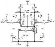
1)- Set P1 to get 20 volts on both output's
2)- Adjust the values of P2/3 by small steps to get 5 volts across Q3
{the current source} and readjust P1
3)- Readjust P2 or P3 to minimize the DC offset
{each output voltage must be as close as possible, a 50mV is correct}
Once hot, about 20/30minutes repeat steps 1.2,3
Without input signal, You must have the same voltage on R8/R9
each seeing about 3.75 amps
PS: If you dont have 10 turns pots or more, do the adjusts by very small steps...
Good luck!
Alain.
Welcome in the "Zen world!"
0)- Before power-up, set values to maximum
1)- Set P1 to get 20 volts on both output's
2)- Adjust the values of P2/3 by small steps to get 5 volts across Q3
{the current source} and readjust P1
3)- Readjust P2 or P3 to minimize the DC offset
{each output voltage must be as close as possible, a 50mV is correct}
Once hot, about 20/30minutes repeat steps 1.2,3
Without input signal, You must have the same voltage on R8/R9
each seeing about 3.75 amps
PS: If you dont have 10 turns pots or more, do the adjusts by very small steps...
Good luck!
Alain.
salam-kaz,
I see my mistake, thousand excuses!!
0)- Before power-up, set values to maximum
1)- Set P3 to get 20 volts on both output's
2)- Adjust the values of P1/2 by small steps to get 5 volts across Q3
{the current source} and readjust P3
3)- Readjust P1 or P2 to minimize the DC offset
{each output voltage must be as close as possible, a 50mV is correct}
Regards.
Alain.
salam-kaz said:(1) What is an initial value of P1, P2 ,P3(10k pot.)
(2) Which pot.(P1, P2 P3) Should I adjust first?
Kaz San,
I also see Japanese flag first time in this forum. Welcome!
I would have initial values of
(1) P1=P2=8K
(2) P3=3K
And, will follow this steps:
(3) Increase P3 until get 30V across R8
(4) Increase P1 a little bit until get 9V at the gate of Q1 referring to the ground
(5) Adjust P2 until see the lowest offset voltage bewteen the two output nodes
By the way, are you using IFRP240 . . . ?
Hi, Babowana san, how do you do?
Thank you very much for the advice.
>By the way, are you using IFRP240 . . . ?
Actually, before buying IRFP240, I am trying on my prototype with FS22SM(Mitsubishi), and 2SK2371(NEC) which I found from scrap(junk?) power supply circuit board. It seems they have close max rate but different output characteristics(Id-Vds).
And today, my first attempt was unsuccessful. Smoke came out. Maybe I should draw a load line and think about more carefully.
>(3) Increase P3 until get 30V across R8
Increase P3 goes to increase Ids of Q3?
Kaz
salam-kaz said:Increase P3 goes to increase Ids of Q3?
Yes, Kaz san.
Sorry about the smoke.
I thought that you were playing with IRFP240.
I just checked datasheet of FS22SM(Mitsubishi), and
found Vgs(th) lower than IRFP240. Please, start with
lower P3 value, e.g. about 1K.
I think you don't need to worry about Q1 and Q2.
Their Vgs will be set according to the Id value (current
source bias) which will be decided by Q3 (current source).
I hope you will use "heat sinks big enough."
Good luck.
I am very intersted in your result . . .
Hi, everyone.
Today, I conducted pre-test for the second trial.
This time, I used lower power supply (24V) and lower idle current (1A for each FET: 2SK1938).
The result was very successful. I could adjust easily and hear music from CD. I hope the second trial will also go smooth. One thing in my mind is whether the heat sinks are big enough or not�c
Kaz
salam-kaz.
Glad all is working fine.")
The heatsinks size depend on how much power you have to dissipate,
What are the sizes, and possibly model of your's ?
Alain.
And don't worry:
"Smoke is part of the learning process, every one of us did, even once!"
I did blow the surge protection on my SE yesterday!
Glad all is working fine.
The heatsinks size depend on how much power you have to dissipate,
What are the sizes, and possibly model of your's ?
Alain.
And don't worry:
"Smoke is part of the learning process, every one of us did, even once!"
I did blow the surge protection on my SE yesterday!
Alain san
Thank you for the reply.
I use �g50mm x 115mm x 160mm�h heat sinks for each MOSFET. A rough calculation shows the thermal resistance is around 1deg C/W. So to satisfy the original spec., I think I might need forced cooling by fan. In Nelson�fs original paper, it says, �g This would be achieved by heat sinking with a thermal resistance of about 0.15 deg C. Per watt.�h Is this for the power resistors?
Kaz
salam-kaz,
If I remember correctly the ZV7 draws 375 watts
1) Each Resistor 8 Ohms * 3.75A ==> 112 Watts *2pieces = 224 Watts
3) The Mosfets take the rest... 150 Watts
\So Q1/Q2 3.75A * 15 Volts = 56 watts for each
\Q3 the current source 3.75*2 *5Volts = 37.5 watts
Your heatsinks seams good for the MosFet's
But you need bigger ones for each resistor or a fan
The 0.15 Nelson explains if for the total 375 watts dissipation {HOT!!!}
40 degrees over ambiant 375 watts ==> would need 40/375 = 0.107 {deg C/watt}
heatsink, for total dissipation...
Each resistor needs about: 40/112 = 0.36 {deg C/watt} heatsink each
Q1/Q2 35/56 = 0.625 {deg C/watt} heatsink each
Q3 35/37 = 0.93 {deg C/watt} heatsink
A fan on the 2 resistor heatsink will be better. choose a silent one...
PS: Note at this point you have only one channel working...
Happy building.
Alain.
salam-kaz said:Is this for the power resistors?
Alain gave you very good reply.
Yes, Papa says that separate heat sinks for power Rs are often advantageous. 224W is from the two power resistors and if room temp is 30 deg, 0.15 x 224 + room temp. is about 60 deg.
Alain san, Babowana san
Thank you for detailed explanation.
For each power resistor, I use nine 40w cement resistors. So, totally, 36 resistors are on the aluminum plate!! Simply because I can�ft afford Dale�fs or that kind. Each resistor dissipates about 12w. I wonder how hot will it be�c And tomorrow, time for the second trial! Let's see what will happen?
Kaz
- Status
- This old topic is closed. If you want to reopen this topic, contact a moderator using the "Report Post" button.
- Home
- Amplifiers
- Pass Labs
- ZV7R: Question from beginner