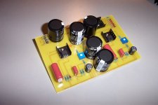
I have checked the PCB for a couple of times and couldnt find any short circuits as well as wrong polar. But I still got blown up for these resistors (R2, R3). Dont know what to do next !!!
Do I have to isolate the transistors from the heat sink? The heat sink is very small and do not connect to anything else.
Do I have to isolate the transistors from the heat sink? The heat sink is very small and do not connect to anything else.
hello,
BOZ should work with any TO-220 NPN transistor like BD243 (in my case). TIP41 have same pinout as TIP29, so go with it.
If your heatsinks are not touching other parts on the board (or the chassis), you don't need any isolation between heatsink and transistor case. Just don't forget adding some silicon grease")
Try disconnecting R2/R3 and measuring voltages around Q1. You would expect something like 85VDC across C1, 60VDC on Q1 emitter.
If these voltages are OK, something in preamp is drawing more power than supply can provide.
As previously said, try powering up one channel at a time and see what happens.
BOZ should work with any TO-220 NPN transistor like BD243 (in my case). TIP41 have same pinout as TIP29, so go with it.
If your heatsinks are not touching other parts on the board (or the chassis), you don't need any isolation between heatsink and transistor case. Just don't forget adding some silicon grease
Try disconnecting R2/R3 and measuring voltages around Q1. You would expect something like 85VDC across C1, 60VDC on Q1 emitter.
If these voltages are OK, something in preamp is drawing more power than supply can provide.
As previously said, try powering up one channel at a time and see what happens.
The plate can be used as middle pin? and in this case, the middle pin is just no use?
You refer to the transistor's tab? For TIP41 transistor, tab is connected internally to the middle pin (collector). If transistor is making electrical contact via the screw and nut to the copper pad, you can left the middle pin disconnected.
After removing the resistors, I got voltage at C1 is around 80V, emitter of Q1 is around 60V, BUT, after about 10mins, the C2 is exploded. Definitely there is some shorting somewhere.
So I decided to redo it from begining which I will test as I go, and very careful about the short circuit. :-(
@Dzoli: Did you get the same problem as mine before you change to 22K?
So I decided to redo it from begining which I will test as I go, and very careful about the short circuit. :-(
@Dzoli: Did you get the same problem as mine before you change to 22K?
After removing the resistors, I got voltage at C1 is around 80V, emitter of Q1 is around 60V, BUT, after about 10mins, the C2 is exploded. Definitely there is some shorting somewhere. So I decided to redo it from begining which I will test as I go, and very careful about the short circuit. :-(
Hello,
No, I relised that the current drawn form the the power supply was high on on channel. I had the possibility to compare the voltages between the two channels. Then I found the faulty 10K trimmer.
Regards,
Zoltan
Hmm, electrolytic caps explode if they build excessive inner pressure. This may indicate reversed polarity on C2, faulty C2 or so...after about 10mins, the C2 is exploded.
I would replace C2 with new one, 100uF/100V.
After that, check voltages as previously mentioned. When you're sure about the supply, solder back R2/R3 and check. You might expect voltages similar to this
thread
Fun with Blackies
Hi
Just for the record. Yesterday I replaced originals coupling 1.0 and 10,0 uF Panasonics to Black-Gate N 50V 1.0 and 4.7uF.
Well it really works. Improved highs and sound stage.
Recommended.
Happy New Years
likeDIY said:Hi guys, the output capacitor C103 =10uF can be changed by 22uF? Will the output frequency response changes alot?
Hi
Just for the record. Yesterday I replaced originals coupling 1.0 and 10,0 uF Panasonics to Black-Gate N 50V 1.0 and 4.7uF.
Well it really works. Improved highs and sound stage.
Recommended.
Happy New Years
Those BG are e-lyts right?Still they sounded better than the Panasonics?Yesterday I replaced originals coupling 1.0 and 10,0 uF Panasonics to Black-Gate N 50V 1.0 and 4.7uF.
- Status
- This old topic is closed. If you want to reopen this topic, contact a moderator using the "Report Post" button.
- Home
- Amplifiers
- Pass Labs
- BOZ preamp project