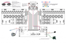
I'm having trouble posting the Cabling file....I'll see what the problem is and send it later.
Anyway this complete schematic will answer all your component questions i think.
C
I think this will help, or give me your email via pm (4MB pdf)
")
denis
Attachments
yep!..be carefull that you have the power supply adapted for the relays you intend to use!...you can use whatever voltage you want; 12V or 24 but power supply has to correspond.
I want to re-emphesize the suggestion of CeeVee, because I learned that the hard way with Cheff UGS amp.
The 'default' BOM and Premp has one flaw: The logic&relais power supply can not cope with all possible choice of parts. Load on the 78xx can also be too high. It depends on what display and relais you choose.
In my case, I chose a VFD Display. The load on the 7809 and it's dissipation was high. Both the transformer and the 7809 got very warm, and so the power supply died within the first year. After power supply repair, the 7809 died a bit later.
Since I didn't want to give up the nice VFD display and the already soldered relais, I decided to change from 78xx to DC/DC converters. The lower dissipation loss of the DC-DC converters solved my problems - power section stays cool.
Since I didn't want to give up the nice VFD display and the already soldered relais, I decided to change from 78xx to DC/DC converters. The lower dissipation loss of the DC-DC converters solved my problems - power section stays cool.
I think the VFD with 78xx doesn't work well, I've got a DC/DC TracoPower also
Has anyone thought about a new group buy? This still seems like a wonderful preamp
I am interested, anyone elese
I like to use DALE RN55 everywhere, including the commuted ladder attenuator.
So I didn't questionned myself about that.
It seems that you are not satisfied with the resulting sound.
You may be have some other problem that have to be solved first.
Using standard metal film resistors, the sound was already astounding (compared to live sound of classic music), so I permit myself to ask.
Can you post some pictures of your preamp version please (in particuliar the Cheff's UGS modules) ?
I’m in process of sourcing components for the UGS v3 modules, I want to use Dale RN series resistors as recommended in the Maousse’s post, the BOM list “UGS_liste de courses_Cheff.xls” include other Dale resistor series that seems to be rated at 600mw. The Dale RN55 series resistors is rated at 125mw and RN60 is rated at 250mw both has dimensions that will fit on the UGS v3 board, but higher power rated resistors will not.
What is the power requirement for the resistors?
Is the same power for all resistor or there some that must have a different power value?
Thanks,
Alejandro
UGS module v3 resistors power requirement
Thank you for the info about resistors power, I will share the answer so everyone can have this info:
1/8W resistors are ok
1/4W are easier to read markings
Only the 4R7 in the power line should be 1/2W if it blows. I just kept 1/4W but take care of discharging the caps before connecting the external power supply.
The Thursday earthquake is still here, yesterday night we have a big “replica” of 7.6 Richter degrees and more than 200 replicas of lower intensity have been measured since the main earthquake. Thanks for your concern.
Regards,
Alejandro
Hi Alejandro,
I answered to your MP.
Take care in Chile
Cheers
Thank you for the info about resistors power, I will share the answer so everyone can have this info:
1/8W resistors are ok
1/4W are easier to read markings
Only the 4R7 in the power line should be 1/2W if it blows. I just kept 1/4W but take care of discharging the caps before connecting the external power supply.
The Thursday earthquake is still here, yesterday night we have a big “replica” of 7.6 Richter degrees and more than 200 replicas of lower intensity have been measured since the main earthquake. Thanks for your concern.
Regards,
Alejandro
Hi potepuh, sorry for the late answer.
The schematic you are showing is not the design we talk in here.
Without more info, I can only say they should allow less a milliamperes in the bases of the BC550C
So roughly, for 24v relays, make it 27k
This design is from member NAR.
He was not using relay atenuator but a rotary one ?
This is an attempt to simplify the preamp and remove display and relay atenuator.....would be nice to try it with the new chips Nelson uses on his XP 30 for volume control.
Should be the very essence of UGS sound.
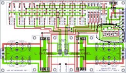
on problem CeeVee, it was just longer to figure it out with just the pcb.
The 3 transistors he needs RB value is for a discrete OR gate to command the unbal relay.
About 1mA in the base is fairly enough to saturate the transistor.
I guess there is a topic on this other design ?
Moderators hereby ?
The 3 transistors he needs RB value is for a discrete OR gate to command the unbal relay.
About 1mA in the base is fairly enough to saturate the transistor.
I guess there is a topic on this other design ?
Moderators hereby ?
on problem CeeVee, it was just longer to figure it out with just the pcb.
The 3 transistors he needs RB value is for a discrete OR gate to command the unbal relay.
About 1mA in the base is fairly enough to saturate the transistor.
I guess there is a topic on this other design ?
Moderators hereby ?
No it's this Thread: http://www.diyaudio.com/forums/pass-labs/86300-ugs-adventures-100.html#post2741050
If you need details PM NAR, he's very helpfull.
I would certainly try it with MUSES volume control : link should sound amazing!
Last edited:
22.1K but the exact value is not critical. As you probably figured out already, the corresponding transistor controls a relay that shunts the unused IN- signal to ground when an unbalanced input is selected.Anyone knews the value off the RB resistor.
B.t.w. the UGS pre is well worth building. It did raise the transparency of my system. There was no turning back to the BLS, which is quite nice in its own right.
If anyone is interested in the UGS but need more gain, you can use two UGS in series. For volume control, wire a pot (10K) in shunt configuration between the + and - signals between the gain stages. As a side benefit, the input and output impedances then become volume-independent. I would be happy to provide details if anyone is interested. I've built it and it works nicely.
Pierre
This design is from member NAR.
He was not using relay atenuator but a rotary one ?
This is an attempt to simplify the preamp and remove display and relay atenuator.....would be nice to try it with the new chips Nelson uses on his XP 30 for volume control.
Should be the very essence of UGS sound.
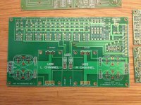
NAR and me, with permission from Mr. Pass. Our boards were black. I saw a green board above. Hopefully it was sourced through DIY channels, and not for profit. I will post some pictures of my build so you can get a feel for what the end product can look like.
- Home
- Amplifiers
- Pass Labs
- UGS adventures