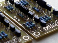
Good to read that some more fanatics have choosen this project. The UGS preamp is a very nicely and absolutely professionally developed and planned project, - thanks Francois! And thanks Manu for your support and encouragement! I have made my own boards, some were milled the rest was etched. Most stuffing and soldering is done already. Now I do the case and have started with the backplate. Here are a few pictures of my build.
Greetings to all, Martin
Very nice job and very careful work
")
Be careful the external lines on the UGS boards not to short circuit with the real V+ / V- tracks just nearby. I would remove that ext line totally with gentle abrasion process, but if no electrical short should be OK
nAr
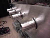
awpagan: No, not in this case as each heat sink carries just one transistor. All the heat sinks will be electrically life, but they are not connected to another part of the circuit via the board.
nar: Thanks for the hint. Yes, that would be a stupid mistake. Especially so, as I always strive for excellent quality.
Cheers, Martin
nar: Thanks for the hint. Yes, that would be a stupid mistake. Especially so, as I always strive for excellent quality.
Cheers, Martin
Attachments
awpagan: No, not in this case as each heat sink carries just one transistor. All the heat sinks will be electrically life, but they are not connected to another part of the circuit via the board.
Cheers, Martin
It's just not good work practice to leave the heatsinks live.
I'm using silpads on mine, and they are not overheating.
Allan
nar: Thanks for the hint. Yes, that would be a stupid mistake. Especially so, as I always strive for excellent quality.
Cheers, Martin
I would remove the line, but if electrically not live, you may leave it
It's just not good work practice to leave the heatsinks live.
I'm using silpads on mine, and they are not overheating.
Allan
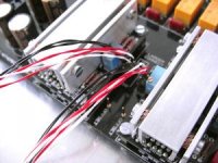
I also use sinks on the PSU, they get just get "gently hot"
This pre doesn't actually need sinks.
One can omit the PSU ones; the UGS board heatsinks are essential to maintain very low offset at the outputs, thus permitting DC coupling with next stage, thisis one of the reasons we use this pre !!!
With the heatsinks temp is about 37 - 38 celsius
Cheers,
nAr
I finished my UGS preamp boards. I have the "simple" version, just the UGS power supply boards and the UGS modules themselves (not the whole preamp with display).
Is there a document, or an explanation of adjusting the modules? I couldn't find one.
The procedure is simple : once module is powered, plug between any output and ground, adjust roughly VR1 20R to get 0 mV offset at the output. Then placing multimeter between the 2 outputs, use VR2 to achieve 0 mV differential.
You'll have to reproduce the procedure about 6-7 times to get both absolute and relative offset 0 mV, because the trimpot settings are interdependant. After one hour or so, it is the good moment to finetune all this. It can be faster if you use 2 multimeters at the same time, one for absolute, one for differential
One thought though : to get stable 0 mV offset, you'll definitely need the heatsink. Without, you can test the module and get about 0 mV at the outputs, but offset will wander. Some friend suggested that the heatsink could link the 2 double jfets and would be just sufficient; I chose to build the "total" heatsink just because I didn't know, and it worked fine.
Another hint is to plug and play the module without the RFBs in place, so if you have problems on the boards then the cause will be easier to troubleshout
I really hope you'll get some working modules at the first time. Mine played music instantly, and I was so happy with the sound, listening to my favorite test CD I could almost cry

In my opinion, with the UGS modules we get the absolute best of this jfet double pair amplification, freed from artefacts like noise, distortion, etc ... thanks to the double cascoding and the current mirror outputs, thus no external output load on the jfets. Supersymmetry does a royal "finish touch" on this, and the result is absolutely musical, with nothing artificial, perfect sense of rhythms and excellent respect of complex tone characters. But it is just a personal opinion
Best,
nAr
Last edited:
...mine has been playing for almost 2 years now and i can completely agree with your appraisal nar.....just gorgeous music, of course make sure you have the best source.
This led me to redo the IV on my Shanling.....and build an F5......
Source is very important for sure !
I completely agree with your Shanling mod ... I/V stage is perhaps the node where any improvement is heard instantly.
I'll build an UP next, but will take some time ...
Best,
nAr
The procedure is simple : once module is powered, plug between any output and ground, adjust roughly VR1 20R to get 0 mV offset at the output. Then placing multimeter between the 2 outputs, use VR2 to achieve 0 mV differential.
You'll have to reproduce the procedure about 6-7 times to get both absolute and relative offset 0 mV, because the trimpot settings are interdependant. After one hour or so, it is the good moment to finetune all this. It can be faster if you use 2 multimeters at the same time, one for absolute, one for differential
One thought though : to get stable 0 mV offset, you'll definitely need the heatsink. Without, you can test the module and get about 0 mV at the outputs, but offset will wander. Some friend suggested that the heatsink could link the 2 double jfets and would be just sufficient; I chose to build the "total" heatsink just because I didn't know, and it worked fine.
Another hint is to plug and play the module without the RFBs in place, so if you have problems on the boards then the cause will be easier to troubleshout
I really hope you'll get some working modules at the first time. Mine played music instantly, and I was so happy with the sound, listening to my favorite test CD I could almost cry
In my opinion, with the UGS modules we get the absolute best of this jfet double pair amplification, freed from artefacts like noise, distortion, etc ... thanks to the double cascoding and the current mirror outputs, thus no external output load on the jfets. Supersymmetry does a royal "finish touch" on this, and the result is absolutely musical, with nothing artificial, perfect sense of rhythms and excellent respect of complex tone characters. But it is just a personal opinion
Best,
nAr
Thanks. I'll give it a try. I need to build a heatsink of sorts. I used double 2SK170 and 2SJ74 with BC550 and BC560 so the standard heatsink may be slightly modified.
I'd also become interested in Chas (Hifizen's) version of this circuit, but I'll try the standard first, then move to new things.
Anyone having spare boards for UGS ?
I might be able to help...PM me please
Tony
I also have some spares, from our recently finished UGS project + UGS Motherboard
Best,
nAr
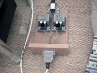
Now in da box n' playing nicely
Ladder connector detail
PSU-ombilical, need to build proper case
Best regards,
nAr
Attachments
I intend to use the Joshua Tree attenuator from twistepearaudio.com in front of the UGS pre. The standard resistor set that can be bought together with the attenuator gives an input impedance between 2,2 kohm and 10 kohm and an output impedance of 750 ohm. I bought the attenuator boards without any parts so I am free to chose the resistors to suit my needs. I am a little worried that 2,2 kohm would be a little low at the input of a pre. What do you think? Should I go for a little higher impedance?
I intend to use the Joshua Tree attenuator from twistepearaudio.com in front of the UGS pre. The standard resistor set that can be bought together with the attenuator gives an input impedance between 2,2 kohm and 10 kohm and an output impedance of 750 ohm. I bought the attenuator boards without any parts so I am free to chose the resistors to suit my needs. I am a little worried that 2,2 kohm would be a little low at the input of a pre. What do you think? Should I go for a little higher impedance?
It might be problematic for your source. I mean, the Joshua model is designed to be placed at preamp output, not input. Standard sources won't like to be loaded with variable impedance and as low as 2,2k. For that reason at UGS input a fixed impedance attenuator of 47k or 50k is preferred.
You can keep the existing resistor values you have, and by placing attenuator at the output it would likely work and would be a better match; UGS won't mind the varying impedance of the ladder. A 10k fixed ladder might be a better solution at the output though.
UGS out impedance is about 125 ohms single ended and 250 ohm differential.
Best,
nAr
You are probably right, I should put the attenuator after the pre.
I will start with these boards since I already have them but later I may try a 10K ladder as well.
Thanks for the answer.
You are probably right, I should put the attenuator after the pre.
I will start with these boards since I already have them but later I may try a 10K ladder as well.
Thanks for the answer.
It will work at the output
For ladder at the input input I mounted two of those for balanced operation in stereo, so far so good
:http://www.audiophonics.fr/potentiometre-commute-welwyn-ladder-stereo-50k-p-5228.html
Best,
nAr
Last edited:
- Home
- Amplifiers
- Pass Labs
- UGS adventures