
Tested again...seems ok now...guess the relays needed a little exercise.
Tested with switches..."crazily fast" as you say Manu...perfect, aha!!! i thought, it's the remote.
Tried remote...same thing ???????????????
I like these "bugs" that go away by themselves...or maybe i had something interfering with the remote, this was what i was using when i noticed it, ...i was using the remote near a window...or the
fluorescent economy lamps ?
They are switched off right now, i still have daylight.
Problem is that i'm getting to know a working UGS....i tend to see gremlins all over the place until i check everything new !
thanks for the feedback guys, now for the serious debugging of my other UGS module.....
hehe...maybe.
But i got a bit of more substantial news; between last post and this one i checked the other module that did not give absolute offset adjust but gave relative adjust....and even played!
I checked all the bias settings and found out that Q12 Vbe was...0V! so Q12 had given up the ghost!
This shows that even if you follow step by step the alignment procedure for the UGS module, this still is possible to creep in, as the doc says we should check Vbe of the transistors only if the specified voltages at the test points is not met.
I would suggest it is changed to require Vbe testing for all bipolars.
After the absolute offset ( which was 245mv and with the new ZTX droped to 84mv ) was adjusted to 0V, the relative offset which was 0V now showed 42mv and needed adjustment ofcourse.
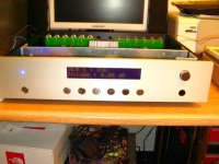
Summing up: it now plays beautifully !
Now to finish the box...waiting for the pushbuttons....from Scoutone.
Hope this detail can save somebody some pain and disapointment.
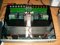
next few days...photo sessions! I'll post some nice pictures.
But i got a bit of more substantial news; between last post and this one i checked the other module that did not give absolute offset adjust but gave relative adjust....and even played!
I checked all the bias settings and found out that Q12 Vbe was...0V! so Q12 had given up the ghost!
This shows that even if you follow step by step the alignment procedure for the UGS module, this still is possible to creep in, as the doc says we should check Vbe of the transistors only if the specified voltages at the test points is not met.
I would suggest it is changed to require Vbe testing for all bipolars.
After the absolute offset ( which was 245mv and with the new ZTX droped to 84mv ) was adjusted to 0V, the relative offset which was 0V now showed 42mv and needed adjustment ofcourse.
Summing up: it now plays beautifully !
Now to finish the box...waiting for the pushbuttons....from Scoutone.
Hope this detail can save somebody some pain and disapointment.
next few days...photo sessions! I'll post some nice pictures.
CeeVee said:hehe...maybe.
But i next few days...photo sessions! I'll post some nice pictures.
We are greedy of it...
UGS Alignment document....thanks to breizheau.
Although i think Vbe checking has to be done anyway, even if all test point Voltages are correct, as my previous post justifies.
http://www.homecinema-fr.com/forum/download/file.php?id=56065

Although i think Vbe checking has to be done anyway, even if all test point Voltages are correct, as my previous post justifies.
http://www.homecinema-fr.com/forum/download/file.php?id=56065
 Thats very impressive work indeed ... Kudos one more time ...
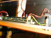
lll said:... You help me many times even if you d'ont now about. ...
Thanks, you're welcome
 ... even if I can't believe it ...
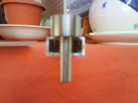
look the picture (not very good).
Indeed
 I can't determine how you fixed the push knob to the push button on the uC board ... glue?
I am looking for an simple method to do that ...
otherwise my UGS the casing of my UGS will never be finished

I ll post some pictures more about knobs beaucase my english it's not good to describe...
Thx please.
Manu
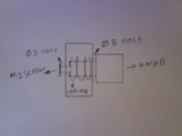
the rectangular piece of alu dimension is 1cm by 2cm and 18cm long,
i drill in one "2cm face" 3 holes of 3mm dia (two in the edge one in the middle) in order to attach in the front panel drill (blind hole)and tap for
M3 screw i make also 6 holes 8mm dia for the knobs and the springs.
in the other 2cm side i make 6 holes 3mm dia just for the screws M3 attach them in the knobs (drill and tap the neck of the knobs after the cut of the neck leave aprox 1cm long) with the M3 screws in the knobs you can adjust the gap between the buttons of the pcb and the knobs also hold the knobs in position.
between the front plate and the piece of alu i put 1 rondell this space between of them is the "travel" of the knobs.
after that i marked the support holes of the pcb in the in the same piece alu drill and tap for M3 screws. in the picture is the black spacers.
Attachments
Thanks for detailled description
Just one last question/confirmation : the spring goes through the 8mm hole to meet the inner side of the knob, right?
I think I will give it a try....
And the fact that your knobs are plain furniture knob will make them easily available I guess...
Good idea
THX
Manu
Just one last question/confirmation : the spring goes through the 8mm hole to meet the inner side of the knob, right?
I think I will give it a try....
And the fact that your knobs are plain furniture knob will make them easily available I guess...
Good idea
THX
Manu
- Home
- Amplifiers
- Pass Labs
- UGS adventures