...hehe yes Cheff did flash Eeprom, don't often fall twice in same trap.
I will try as you say to test the display on slim version today evening.
will keep you posted.
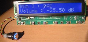
It's odd because i think the board must be working correctly, it seems that the display data lines get corrupted somehow.
These were the first pins i checked at the processor but the solder looks perfect....even if i say so myself.

I will try as you say to test the display on slim version today evening.
will keep you posted.
It's odd because i think the board must be working correctly, it seems that the display data lines get corrupted somehow.
These were the first pins i checked at the processor but the solder looks perfect....even if i say so myself.
Update:
...not good, had another crystal fontz display so tested with it ( faster than making an adapter and testing with the slim version ).
result was exactly the same....so not a faulty display module!
-manual reflow solder of the controller again.
-Reflash controller, remembering to load Eeprom data as well!
-Tested.......
Same result.
By the way, i used exactly same fuse settings for this display as for the optrex, i assume this is right.
HI CeeVee,
Sorry for that...
Yes, the fuse settings are the same.
I don't have any clue where it could come from , except it looks like a timing problem...
Is your crystal a 4MHz one ?
Have you any possibility to check wether it is oscillating at the right frequency ?
Checked the 5V voltage on µC pins ?
Checked the solder joints on the LCD connector ?
Continuity between the µC pins and the LCD pins ?
Once again, I tested a pcb from the same batch as yours (from the "international" GB), and it worked perfectly with the crystalfontz display...
And Yunick had it working with the same board and optrex display : http://www.diyaudio.com/forums/showthread.php?postid=1538175#post1538175
Could you post some hi-res shots of the board, mainly the µC zone and the lcd connector zone (both sides) ?
Sorry for that...
Yes, the fuse settings are the same.
I don't have any clue where it could come from
, except it looks like a timing problem...Is your crystal a 4MHz one ?
Have you any possibility to check wether it is oscillating at the right frequency ?
Checked the 5V voltage on µC pins ?
Checked the solder joints on the LCD connector ?
Continuity between the µC pins and the LCD pins ?
Once again, I tested a pcb from the same batch as yours (from the "international" GB), and it worked perfectly with the crystalfontz display...
And Yunick had it working with the same board and optrex display : http://www.diyaudio.com/forums/showthread.php?postid=1538175#post1538175
Could you post some hi-res shots of the board, mainly the µC zone and the lcd connector zone (both sides) ?
Sure Cheff,
I'll check that and put up some Hi-res shots ....who knows, might help somebody else down the line.
The cristal is 4Mhz, came in the same batch as the slim ( working ) version.
Yesterday i even checked if using the 16AU version instead of the 8AU could be the culprit.
Today will be a long day at the office for me ...but during the next couple of days i'll do all that, here at the ATC center i have all the equipment i don't have at home...hehe.
thanks for being there.
CheffDeGaar said:Well, if I understand correctly, you tried two different µcontrollers with no results ?
I'll be on vacation for 10 days on saturday, so I won't be able to check whatever
But we'll try to find out before this time, or you'll be on your own for a moment
NP Cheff, I've solved many more complex issues, my "call for help" was only to speed up things.I have some hope that you might be right with the timming issue, will try asap.
As for processors, no! only resoldered the same one.
Result remains so it can be selectively fried?! ie: can be programmed but outputs wrong data ?
The Crystalfontz display cannot be at fault because dispaly with optrex is exactly the same.
...seriously: have a very nice holidays...i hope to have pictures with music ( me enjoying the music ) when you get back.
Re: using UGS preamp for F4
Depends
Will you use it balanced (in & out), unbalanced (in & out) or a combination of thereof...
Best is to try it as is, and if you think the gain is too low, increase the RFB resistors to 68K,75K or 82K and check again.
The percepted gain is a matter of taste, and depends on the output level of your source, the gain of the amp and the speakers' efficiency...
If you happen to know all these figures, just tailor the gain to your needs using the formula given here (page 14)...
Cheers
Hi Jim,jims said:Hi Cheff
I was trying to follow the early parts of this thread to figure out the best combination of resistors for high gain. I am afraid I got lost. Please tell me what setup you would recommend to use the UGS as a preamp for the F4.
Thanks
JimS
Depends
Will you use it balanced (in & out), unbalanced (in & out) or a combination of thereof...
Best is to try it as is, and if you think the gain is too low, increase the RFB resistors to 68K,75K or 82K and check again.
The percepted gain is a matter of taste, and depends on the output level of your source, the gain of the amp and the speakers' efficiency...
If you happen to know all these figures, just tailor the gain to your needs using the formula given here (page 14)...
Cheers
CeeVee said:I have some hope that you might be right with the timming issue, will try asap.
It was just an idea... Had to debug a weird board, where the crystal was a 7.3MHz instead of a 4MHz one. Even with this short timings, the display was working, and only the IR reception was out of track...
As for processors, no! only resoldered the same one.
Result remains so it can be selectively fried?! ie: can be programmed but outputs wrong data ?
Had the case too, where two output pins were fried, while the µC programmed OK.
That's why I'm more and more sure that the µC had a bad day somewhere during the porcess
...seriously: have a very nice holidays...i hope to have pictures with music ( me enjoying the music ) when you get back.
Thanks
And I hope you'll get it worging soon
Cheers
Well Cheff is enjoying his day in the sun.....but here is the result of my microsurgery efforts to replace the ATmega 64.
Indeed the other one had had a bad day....even though i was "sure" i had taken all reasonable precautions.
now for putting it all together, rest of the boards are populated....
more news next week.
Indeed the other one had had a bad day....even though i was "sure" i had taken all reasonable precautions.
now for putting it all together, rest of the boards are populated....
more news next week.
Attachments
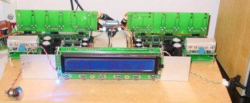
It's alive (the case needs some work though)!! '')
This would have to be one of the the harder DIY projects I have attempted, and I must say it's a relief not to have destroyed something (the kids knew not to go into the workshop when soldering those SM components).
Thank-you for those who did the design work and made the group-buy possible, and for providing hours of reading (this is a very long tread with tidbits of info all the way through).
I do have question which someone may be able to help with, what would be the best way to configure the UGS module to be an unbalanced to balanced converter. I have build two additional modules for this purpose and am quite keen to use them to provide balanced out put for my Pearl.
Cheers
Paul
')This would have to be one of the the harder DIY projects I have attempted, and I must say it's a relief not to have destroyed something (the kids knew not to go into the workshop when soldering those SM components).
Thank-you for those who did the design work and made the group-buy possible, and for providing hours of reading (this is a very long tread with tidbits of info all the way through).
I do have question which someone may be able to help with, what would be the best way to configure the UGS module to be an unbalanced to balanced converter. I have build two additional modules for this purpose and am quite keen to use them to provide balanced out put for my Pearl.
Cheers
Paul
An externally hosted image should be here but it was not working when we last tested it.
Attachments
In the case of a bare UGS, just follow Papa.
In the case of the All Inclusive version, no need for that, the µC does the work !
When an input has been declared as unbalanced, a relay grounds the - input. One can even select to add +6dB to compensate the level (it's just a numeric offset in the relay activation of the attenuator ladder ).
To all DIYers on that project, do check the setup menu of the µC board, it's full of options
The UGS is a wonderful converter for balanced/unbalanced input or output. I love it!
Just don't forget that the UGS has gain !
Hi Guys,
Connected everything...minus UGS modules.
Relays seem to work ok.
But I'm a bit confused with the testing of the triggers.
With no inputs connected, should i be able to see the voltage on the trigger outputs ?
Sould both right and left amps allways be on ?
My problem is that i don't have the software menu structure.
...and i don't get any voltage on the trigger outputs.
Hi CV,
Glad you sorted it out, and sorry for the blown µC
Triggers deliver short 5V pulses, so, unless you get an oscilloscope, you won't be able to measure anything.
The 3.5mm stereo jack for triggers is wired as follow :
tip -> Pulse out from ugs
intermediate ring -> State of the external device (5V=On, Gnd=Off)
outer ring -> GND
Pulses are sent if the requested state of the triggered devices is not the right one : if the device is off and must be on, or if it is on, and must be switched off, otherwise pulses are not sent.
On power up, the ugs scans the state of the amps (left and right), and if they're off, it outputs a trigger on both jacks (Left amp and right amp)
If the stanby/on switch is pushed twice within two seconds at power up, the "Head amp" jack is scanned, and if it is off, a trigger pulse is issued on the middle jack, and no pulses are sent to the amps
A trigger pulse is also sent to the startup input (the corresponding jack 1-4) at power up.
If an input is chosen during normal functionning, a trigger is sent to the "old" source device to switch it off, then a trigger is also sent to the newly selected source device to switch it on.
This latter behavior is configurable through the "input" menu, with the "activate trigger" option on each input. When this option off, no pulses are sent and the states are not scanned.
At power off, the µC scans all the connected devices, and if they're on, a pulse is sent to the device to switch it off.
Last, with the ugs in standby mode, holding the power switch pressed and pushing the "bypass" button will send a trigger pulse to the amps. This allows to switch on & off the amps to listen to the bypassed input. (Pressing the bypass key on the remote when all is off has the same result)
And the idea of a little circuit to use with the ugs triggers system :
http://psykok.homelinux.org/diy/preamp_ugs/Atours/TriggerCircuit.gif
Hope this helps
Hi Cheff.....holiday too short was it ?
Yeah sorted it out...guessed triggers were not level latches....after datasheet investigation.
It seems i have a fully working ...Miope UGS.
Now to test the heart of it...the audio stuff, will get onto calibrating the UGS modules.
Triggers are essential to me because i want this preamp to switch on an ATI 6012 that powers my ORION+s and the Linkwitz Analog processor.....
- Home
- Amplifiers
- Pass Labs
- UGS adventures