The long awaited post ")
Thanks Chad for bringing some fresh air here
Your concerns are quite interesting, may I say. First, the Vbe balancing in the current mirrors transistors has worried me a litlle, as well as the somewhat low gain of the ZTXs, but quick simulations showed me higher hfe and better hfe linearity, along with similar Vbe didn't improve distortion results in a significant way (hard for me to say that a -95dB H3 is audibly better than a -92dB...) . I know I should not trust simulations
BTW, paralleling "output" transistors is a nice idea. My only fear here is that the amount of the JFets' output current diverted to steer all the mirror's transitors might degrade the advantage of a better matching of operating conditions. But I have to write down some pieces of equations to see if I'm not saying dumb things...
I'm eager to read you about your Wilson/Wildar comparison, as I've no clues on how it would act on the circuit as a whole...
As it seems to be one of your main concerns, may be another way to reduce distortion would be to improve the casodes. In the way they are originally implemented, they are not true cascodes, as the Jfets' drain current dependance on Vds still exists, although minimized. Adam (Acaudio), the real author of these DIY ugs, used Jfets as cascodes, maintaining a better Vds=cst function. May be it's worth a try
I agree that lowering the output impedance is important, and the way you achieved it is quite clever. As the Early voltage of the output transistors is quite high, the output impedance of the paralleled common emitter stages remains still high, and lowering Rout is the only way to reduce Zout. As the gain of the "equivalent" mirror is higher, that's something you can afford, and it has very very nice effects on the DC offset stability, as you have noticed.
BTW, the CL Zout can not be reduced in large ways, as it also depend on the feedback network. Assuming a JFet ym of 25mS, and a gain of your current mirrors of 4.8, my calculations give a Zout differential impedance of 100 Ohms, which seem to match your measurements (supposing the 55R you give is the SE impedance). And that's a really nice value, you halved mine
To sum up, that's a really nice evolution of the circuit, and it will be hard to wait until you post your listening impressions... Thanks for sharing
Cheers
P.S. : Chad, as you happen to live in Canada, may be you can read French, so there's a little attempt to get some equations out of the circuit...
Thanks Chad for bringing some fresh air here
Your concerns are quite interesting, may I say. First, the Vbe balancing in the current mirrors transistors has worried me a litlle, as well as the somewhat low gain of the ZTXs, but quick simulations showed me higher hfe and better hfe linearity, along with similar Vbe didn't improve distortion results in a significant way (hard for me to say that a -95dB H3 is audibly better than a -92dB...) . I know I should not trust simulations
BTW, paralleling "output" transistors is a nice idea. My only fear here is that the amount of the JFets' output current diverted to steer all the mirror's transitors might degrade the advantage of a better matching of operating conditions. But I have to write down some pieces of equations to see if I'm not saying dumb things...
I'm eager to read you about your Wilson/Wildar comparison, as I've no clues on how it would act on the circuit as a whole...
As it seems to be one of your main concerns, may be another way to reduce distortion would be to improve the casodes. In the way they are originally implemented, they are not true cascodes, as the Jfets' drain current dependance on Vds still exists, although minimized. Adam (Acaudio), the real author of these DIY ugs, used Jfets as cascodes, maintaining a better Vds=cst function. May be it's worth a try
I agree that lowering the output impedance is important, and the way you achieved it is quite clever. As the Early voltage of the output transistors is quite high, the output impedance of the paralleled common emitter stages remains still high, and lowering Rout is the only way to reduce Zout. As the gain of the "equivalent" mirror is higher, that's something you can afford, and it has very very nice effects on the DC offset stability, as you have noticed
. BTW, the CL Zout can not be reduced in large ways, as it also depend on the feedback network. Assuming a JFet ym of 25mS, and a gain of your current mirrors of 4.8, my calculations give a Zout differential impedance of 100 Ohms, which seem to match your measurements (supposing the 55R you give is the SE impedance). And that's a really nice value, you halved mine
To sum up, that's a really nice evolution of the circuit, and it will be hard to wait until you post your listening impressions... Thanks for sharing
Cheers
P.S. : Chad, as you happen to live in Canada, may be you can read French, so there's a little attempt to get some equations out of the circuit...

CheffDeGaar said:Your concerns are quite interesting, may I say. First, the Vbe balancing in the current mirrors transistors has worried me a litlle, as well as the somewhat low gain of the ZTXs, but quick simulations showed me higher hfe and better hfe linearity, along with similar Vbe didn't improve distortion results in a significant way (hard for me to say that a -95dB H3 is audibly better than a -92dB...) . I know I should not trust simulations
I didn't do any THD simulations or tests to check if my intuition is correct or not (not that I trust a sim for that info anyway). In theory, the Ve matching, higher hfe and better hfe linearity should each make an improvement. I'm going 'on principle' here, thinking that if it makes a difference, great, if not, then nothing lost. Ditto for using identical devices for the output and reference transistors. I was initially tempted to use a beefier device such as BD139/BD140 or A1837/C4793 for the outputs, but instead went with my intuition that even though the mirror reference and output transistors are operating in different regions of their curves, one would still achieve better cancellation of non-linearities with identical devices than with dissimilar devices.
Yet another reason I selected the A970BL / C2240BL pair was their low 1/f noise. This plays directly into the DC performance... While average / long-term DC offset is basically determined by component temperature coefficients (over which we no control for the silicon parts, fortunately their characteristics are inherently well matched, and in a balanced circuit with thermal coupling will cancel quite effectively), a circuit's short-term DC stability is largely determined by the random 1/f noise contributions of the components. The K389/J109 FETs are already very good in this regard, and there are no suitable substitutes anyway, so you get what you get with those. The source resistors on the input FETs are another of the biggest contributors to 1/f in this circuit, so using low noise resistors here really pays off - bulk metal foil or RN60 types (maybe PTF series, some of the Caddock parts, or CMF60's at the very least) will work best. Carbon, SMD, or even cheap metal films here are likely to degrade the DC stability - IMO it's not worth the cost savings to go with anything less than the RN60's.
BTW, paralleling "output" transistors is a nice idea. My only fear here is that the amount of the JFets' output current diverted to steer all the mirror's transitors might degrade the advantage of a better matching of operating conditions. But I have to write down some pieces of equations to see if I'm not saying dumb things...
I'm eager to read you about your Wilson/Wildar comparison, as I've no clues on how it would act on the circuit as a whole...
Yes, the base currents are a source of error which I was concerned with too. This was a factor that led me toward the more linear transistors, in the hope that at least the error current would be more linear, and then on to the use of the Widlar transistor to buffer the error current from subtracting reference current. The situation is indeed exacerbated by the need to run more idle current in the outputs in order to achieve the lower output Z. As mentioned, I was initially thinking of using a larger output device, but the low beta and potentially mismatched Vbe curves led me to reconsider and go with paralleled devices of the same type as the reference Q. In this case, there is a secondary benefit - the 1/f noise of the output transistors is further reduced about 6dB by using 4 devices in parallel. Large junctions in theory do the same thing, though it's harder to find medium power BJTs specified for 1/f noise. It seemed as I was going through the possibilities that the stars were in uncanny alignment with this design. In my experience, it's rare to find such a clean set of compromises, but simplicity and symmetry are key factors.
O/T: Paul Graham has a great little essay on the philosophy of beauty (good taste) and good design here. I was just reading this, and thought he really struck a chord with my own sense of what makes for good design.
As it seems to be one of your main concerns, may be another way to reduce distortion would be to improve the casodes. In the way they are originally implemented, they are not true cascodes, as the Jfets' drain current dependance on Vds still exists, although minimized. Adam (Acaudio), the real author of these DIY ugs, used Jfets as cascodes, maintaining a better Vds=cst function. May be it's worth a try
If you're referring to cascoding with K246/J103 or similar parts by connecting the cascode FET's gate to the gain FET's source (as Borbely does it), I thought of this. However, I'm not at all convinced that it's better. For one thing, these JFETs have a much lower gm than BJTs, so in fact what you have is something like an effective 300ohm resistance at the cascode's source - quite high (and surely somewhat nonlinear). Compare with the 7-8ohms presented by the emitter of a BJT at 3.5mA. Second, connecting a cascode FET in this way puts the gain FET right down into the bottom of it's curves, with a very low Vds. I think the gain FETs will be much happier and more linear operating with a healthy 10V Vds. One could also connect FETs directly in place of the BJTs and thus eliminate the base currents, but again I didn't feel this would be an improvement due to the low gm of the cascode FETs. So I decided your way was better, and stuck with that.
I agree that lowering the output impedance is important, and the way you achieved it is quite clever. As the Early voltage of the output transistors is quite high, the output impedance of the paralleled common emitter stages remains still high, and lowering Rout is the only way to reduce Zout. As the gain of the "equivalent" mirror is higher, that's something you can afford, and it has very very nice effects on the DC offset stability, as you have noticed
BTW, the CL Zout can not be reduced in large ways, as it also depend on the feedback network. Assuming a JFet ym of 25mS, and a gain of your current mirrors of 4.8, my calculations give a Zout differential impedance of 100 Ohms, which seem to match your measurements (supposing the 55R you give is the SE impedance). And that's a really nice value, you halved mine
I calculated 55R (differential, not SE) based on simulated OL gain and then divided the 1K differential Z by the feedback ratio - 'twas a quick back-of-envelope calculation, so I could be off. At some point I will actually measure it. At this point, I'm thinking the OL gain is more than I need, and I may lower the output resistors from 500R per side to something even lower. As it stands, this circuit can swing 'rail-rail' (well, collector-collector, really) on the output, and as you previously noted, this is not necessary for a preamp. I'll probably try 333R by adding a 1K in parallel with each output R.
To sum up, that's a really nice evolution of the circuit, and it will be hard to wait until you post your listening impressions... Thanks for sharing
Cheers
P.S. : Chad, as you happen to live in Canada, may be you can read French, so there's a little attempt to get some equations out of the circuit...
Oui, j'ai étudié le français. Mais, c'est tres difficile de maintenir sans personne pour converser avec. Even now, I need some help from the dictionary to construct a sentence!
 Anyway, I'm sort of expat now, living in the Silicon Valley. I only get to practice when I'm in Carcassone / Narbonne area on vacation...
distortion results...
Finally got some accurate distortion results... in order to tame the noise which was contaminating my previous measurements, I transformer coupled both the input and output of the CUGS rev0.1 circuit (CUGS stands for "Current-mirror UGS", or "Chad's UGS", take your pick - I prefer the latter )
Input transformer is a Cinemag CMLI-15/15PCA, loaded with 12.1K (on hand) across the secondary, plus the input Z of the CUGS.
Output transformer is a Cinemag CMOQ-3H, wired for 2:1 step-down, and the secondary side loaded with 600R.
CUGS circuit is exactly the same as before - it's feedback network provides a net 10dB of gain, which compensates for the insertion loss of the two transformers plus the 6dB step down at the output, so that the overall result is unity gain.
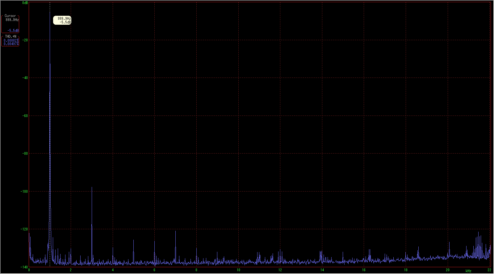
Here's the distortion spectra at 0dBu on the output trafo secondary (my soundcard's 0dBFS is at +5.5dBu), keep in mind this is through both transformers plus the circuit:
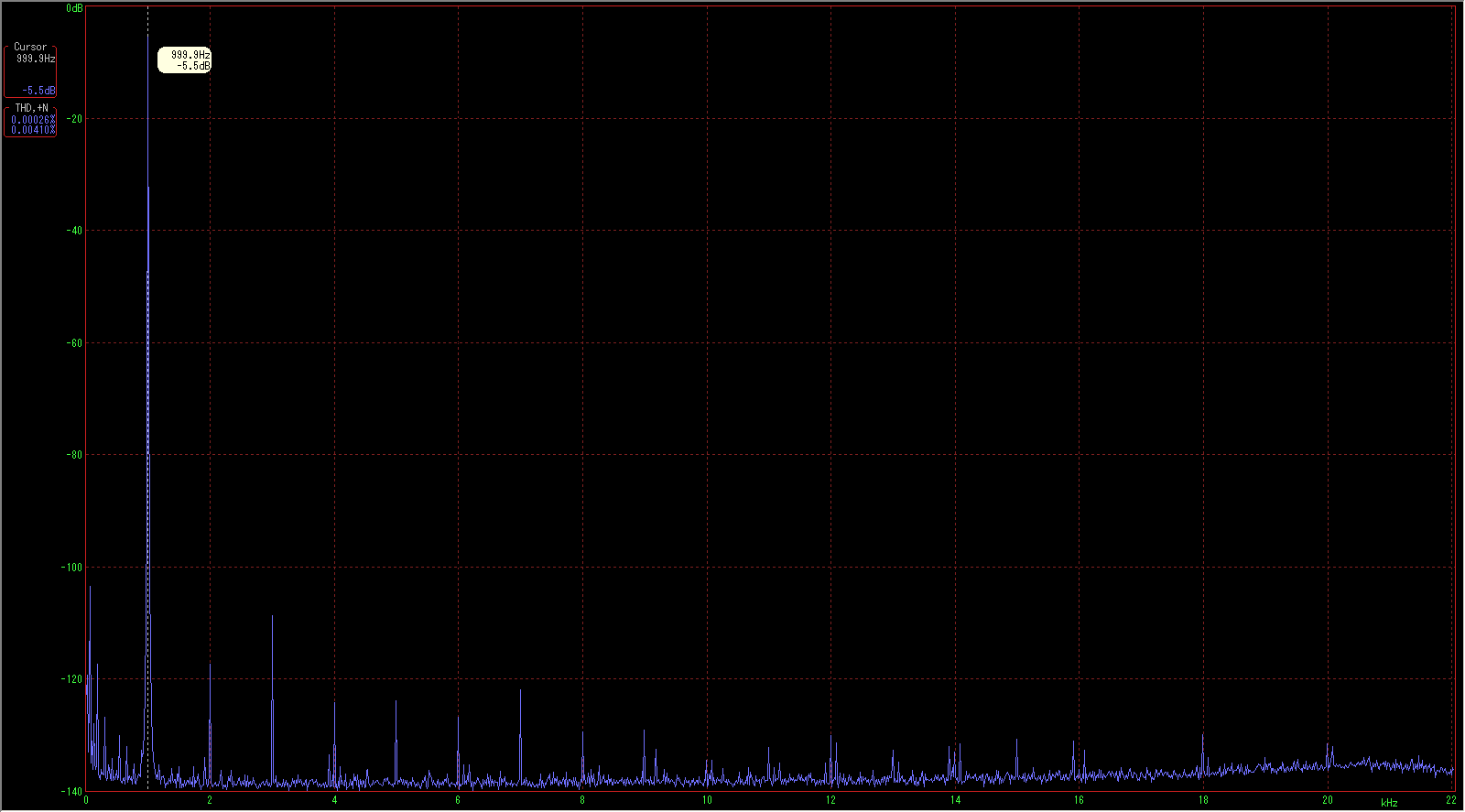
And the distortion residual of the signal generator driving the circuit, measured at the input to the CUGS test setup:
Finally got some accurate distortion results... in order to tame the noise which was contaminating my previous measurements, I transformer coupled both the input and output of the CUGS rev0.1 circuit (CUGS stands for "Current-mirror UGS", or "Chad's UGS", take your pick - I prefer the latter
)Input transformer is a Cinemag CMLI-15/15PCA, loaded with 12.1K (on hand) across the secondary, plus the input Z of the CUGS.
Output transformer is a Cinemag CMOQ-3H, wired for 2:1 step-down, and the secondary side loaded with 600R.
CUGS circuit is exactly the same as before - it's feedback network provides a net 10dB of gain, which compensates for the insertion loss of the two transformers plus the 6dB step down at the output, so that the overall result is unity gain.
Here's the distortion spectra at 0dBu on the output trafo secondary (my soundcard's 0dBFS is at +5.5dBu), keep in mind this is through both transformers plus the circuit:
And the distortion residual of the signal generator driving the circuit, measured at the input to the CUGS test setup:
Uhh... sorry if those plots are a bit big. I'll try to resize them if it can be done without losing too much detail.
OK, as you can see, many of the upper harmonics are already present at the input from the signal generator, so the level introduced by the transformers and the circuit must be very, very small indeed. There appears to be some cancellation of 2nd harmonic happening, so we can infer that the CUGS circuit is producing some which is opposite in phase to the 2HD at it's input. Probably the same with the 4th. The bulk of the distortion is predominantly 3rd, at 10.5dB over the residual of the test setup. There's some garbage off on the right hand edge of the spectrum there - I think it's a measurement artifact, will have to track that down.
Once again, I'm very pleasantly surprised by the performance of this circuit.
SMPTE IMD spectra around 7kHz:
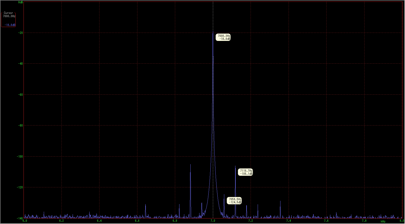
Not too shabby - there is also a grouping of IMD components around 14kHz: the biggest ones are at 13940 and 14060Hz, at -117.3dB each, and a small number of others nearby, all at about -130dB. Not sure how much of that is instrument residual and how much is the real thing.
Anyway, with this kind of distortion performance I don't care to measure much more. I'm thoroughly satisfied that the circuit performs as intended and then some!
My biz trip is on hold for a day or two - if I'm lucky I'll have time to build up the second channel and have a quick listen before I go...
Wooooohooooo!!!!
 Listening bliss!
Couldn't wait till after the trip - I wired up one channel driving both left and right headphone drivers in parallel (Sennie HD600's) - mono, but who cares.
The usually relaxed (sometimes too relaxed) presentation of the HD600s is still there on some level, but the overall character is dramatically different from my previous preamp (single unity-gain opamp w/ buffered output). Where these phones used to sound slightly thin to one degree or another no matter what circuit I drove them with, that trait is now gone. This circuit really brings the 600's to life in a big way - this is one hell of a musical preamp!
The first things I noticed: unbelievable bass (deeeep, powerful, and quick), and huge dynamics! Crescendos that build and build.... and build! Long falling diminuendos which never seem to hit the resolution floor - all the depth and body of the music stays, right down to the bottom. Eye-blinking impacts like I've never heard from these 'phones. I have never before heard dynamics like this from headphones. Pipe organs are just jaw dropping. Something I expected, and is definitely there in spades is that smooth, rich, yet clean, make-you-melt "analog" tone that I've always associated with good discrete and tube circuits. There's no haze or veil, just a very articulate, clean separation of individual sounds (instruments set apart from others, and the tones and inflections of each instrument well defined and clear) - handles delicate sounds with aplomb. Acoustic spaces are readily apparent - around individual instruments and whole bands, even in mono. You can tell what was recorded separately and then mixed together! I'm really starting to dig this - absolutely can't wait to see how it does in stereo on a full system! Another acid test is vocals, and once again, I'm really impressed - male and female alike, solos and chorals are very convincing. Delicious. As Cheff says, the circuit is very quiet, in my case this is even despite the rather noisy power rails straight from my bench supply (and without any local capacitance, even). Of course, high CMRR is to be expected from a balanced class-A circuit such as this, so that raises my confidence that it will be relatively insensitive to the power supply (I'll overdesign it anyway, heh).
As it is, the circuit sounds really incredible, but there are a few things I'll have to address: Upper midrange and treble are a bit hard and need to be tamed a bit - it's clean and smooth, but too forward. I suspect that has more to do with the loading impedance on the secondary of the input transformer than it does with the circuit (which is flat out to 1MHz), so that's where I'll start tuning, and go from there once I've actually got a stereo pair to use.
Unfortunately, I think I've done the opposite of what I'd intended - trying to relieve some of the anxiety I'll have on this trip by getting a little taste before I go!
Cheers once again to Nelson and Cheff!! Hope I can get to sleep now... !

Couldn't wait till after the trip - I wired up one channel driving both left and right headphone drivers in parallel (Sennie HD600's) - mono, but who cares.
The usually relaxed (sometimes too relaxed) presentation of the HD600s is still there on some level, but the overall character is dramatically different from my previous preamp (single unity-gain opamp w/ buffered output). Where these phones used to sound slightly thin to one degree or another no matter what circuit I drove them with, that trait is now gone. This circuit really brings the 600's to life in a big way - this is one hell of a musical preamp!
The first things I noticed: unbelievable bass (deeeep, powerful, and quick), and huge dynamics!
Crescendos that build and build.... and build! Long falling diminuendos which never seem to hit the resolution floor - all the depth and body of the music stays, right down to the bottom. Eye-blinking impacts like I've never heard from these 'phones. I have never before heard dynamics like this from headphones. Pipe organs are just jaw dropping. Something I expected, and is definitely there in spades is that smooth, rich, yet clean, make-you-melt "analog" tone that I've always associated with good discrete and tube circuits. There's no haze or veil, just a very articulate, clean separation of individual sounds (instruments set apart from others, and the tones and inflections of each instrument well defined and clear) - handles delicate sounds with aplomb. Acoustic spaces are readily apparent - around individual instruments and whole bands, even in mono. You can tell what was recorded separately and then mixed together! I'm really starting to dig this - absolutely can't wait to see how it does in stereo on a full system! Another acid test is vocals, and once again, I'm really impressed - male and female alike, solos and chorals are very convincing. Delicious. As Cheff says, the circuit is very quiet, in my case this is even despite the rather noisy power rails straight from my bench supply (and without any local capacitance, even). Of course, high CMRR is to be expected from a balanced class-A circuit such as this, so that raises my confidence that it will be relatively insensitive to the power supply (I'll overdesign it anyway, heh).As it is, the circuit sounds really incredible, but there are a few things I'll have to address: Upper midrange and treble are a bit hard and need to be tamed a bit - it's clean and smooth, but too forward. I suspect that has more to do with the loading impedance on the secondary of the input transformer than it does with the circuit (which is flat out to 1MHz), so that's where I'll start tuning, and go from there once I've actually got a stereo pair to use.
Unfortunately, I think I've done the opposite of what I'd intended - trying to relieve some of the anxiety I'll have on this trip by getting a little taste before I go!
Cheers once again to Nelson and Cheff!! Hope I can get to sleep now... !
Hi CeeVee,
I'm not involved in the now closed Group Buy. I've just drawn the pcbs, and I don't have any spare pcb.
Anyway, if you want to etch your own version, the file is here :
http://idefixes.phpnet.org/illu/av/preamp_ugs/PCBs V3/UGS-V3_pcb.pdf
and for the supply:
http://idefixes.phpnet.org/illu/av/preamp_ugs/PCBs V3/Alim_HCFR_New.pdf
It's the DIY version.
For a more industrial one, with plated through holes, the Gerber files used for the group buy are here :
http://idefixes.phpnet.org/illu/av/preamp_ugs/PCBs V3/UGSGerber.zip
(including the ugs and the supply)
Sorry to be so unhelpful
Cheers
 )
)- Home
- Amplifiers
- Pass Labs
- UGS adventures