Hi Rob
Yesterday evening, I increased feedback resistors from 56K to 100K,
Rin still being 15K, and Rout 1K. The offset stabilty was not affected
by this change (0.1mV stable on both channels when I went to bed...).
But it had heatsinks on, so I can't tell without heatsinking.
On the scope, absolutely no overshoot at 20kHz (the maximum clean
square signals frequency on my generator) with my pcb layout.
I didn't have 150K resistors, so I couldn't test.
Clipping begins to occur around 4V peak to peak at the input (unbalanced).
This morning, I made some listening, and honestly, apart from
a greater gain, so louder sound") , I couldn't find a difference,
, I couldn't find a difference,
but the listening session was somewhat short, so I'll go on this evening.
But as I don't already have two sets of modules to compare, I can
only rely on my memory, and it's not the most impartial judge
Cheers
Yesterday evening, I increased feedback resistors from 56K to 100K,
Rin still being 15K, and Rout 1K. The offset stabilty was not affected
by this change (0.1mV stable on both channels when I went to bed...).
But it had heatsinks on, so I can't tell without heatsinking.
On the scope, absolutely no overshoot at 20kHz (the maximum clean
square signals frequency on my generator) with my pcb layout.
I didn't have 150K resistors, so I couldn't test.
Clipping begins to occur around 4V peak to peak at the input (unbalanced).
This morning, I made some listening, and honestly, apart from
a greater gain, so louder sound
, I couldn't find a difference,but the listening session was somewhat short, so I'll go on this evening.
But as I don't already have two sets of modules to compare, I can
only rely on my memory, and it's not the most impartial judge
Cheers
Hi Cheff
That’s surprising I need to put 10pf parallel to the feedback resistors to avoid overshoot.
Maybe the overshoot has something to do with the BC550/BC560 ?
Which software do you use for simulating.
Tomorrow I listen again to the 1K to ground and compare it.
The best way to try such things is to swap modules.
Maybe mine sounds better now after some burn in time
Rob
Hi Rob,
WRT overshoot, I don't know if the BC550/560 are responsible...
I'd blame it on the perfboard layout, since I found it to be
very layout dependent. Using zetex all along, I've had boards with
overshoot, while other hadn't...
For simulations, I use Microcap (www.spectrum-soft.com)
I agree the best way to compare should be to swap modules, but
unfortunately, I can't for the moment.
And for burn in, I'm pretty close to agree with N.P. :
http://www.diyaudio.com/forums/showthread.php?postid=214567#post214567
Going back to listen
Cheers
Hi all!
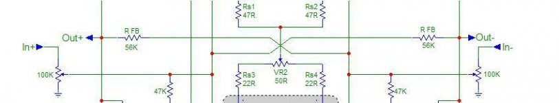
Is there anybody knows the output impedance of this schematic?
I look this schematic for a preamp but I need gain of 6! If I remove the Rin ang directly plug a potentiometer there is not any problems doesn't it ? (Imade a pic )
My first idea was to plug attenuator, like Flat , in output of the UGS circuit but for my application, the output impedance will increase too much!
See you
Is there anybody knows the output impedance of this schematic?
I look this schematic for a preamp but I need gain of 6! If I remove the Rin ang directly plug a potentiometer there is not any problems doesn't it ? (Imade a pic
)My first idea was to plug attenuator, like Flat
, in output of the UGS circuit but for my application, the output impedance will increase too much!See you
Attachments
Hi Cheff
Today I did some measurements and the overshoot is due the 10k on the output not the feedback resistors.
If I return to 1k I don’t have any overshoot.
So maybe the sound difference is from the output resistor to ground and not the feedback resistors or both.
Another problem is that you have overshoot if you connect a cable or put some capacitane to the output.
The overshoot happens from about 100pf to 10n.
That are typical cable capacitane properties.
I don’t have any resistor at the output so maybe you don’t have that problem.
Now I find out what I need for resistor value in series with output or place an RC to ground.
Further I have to wait till my boards arrive for my relay attenuator.
And place it on the output see if there are any difference in sound.
Rob
Hi
I first want to apologise because I made a huge mistake and my previous listening tests are worth nothing.
I accidentally swap the – output with Ground so all my listening where unbalanced out.
What I did yesterday where some listening with balanced out.
And try to get rid of the overshoot on some capacitive loads.
I put 100 Ohm at the output that didn’t help.
Then I tried 2,2pf 4,7pf and 10pf on the 150k feedback resistors.
4,7pf and 10pf is enough to get rid of the overshoot but no cap’s sounded best.
I did comparison between the Theta Six-Shooter and the UGS with SACD.
Had a slight favour for the UGS.
Now I go back to a gain of 5 and do the listening test again.
Rob
Hehe, that's the risk with balanced : too many wires, it feels like defusing a bomb... now shall I cut the green ? or the red ? argh.
Anyway I'm interested in your results !
While I like the idea of SuSy I see two disturbing things in this circuit :
- It behaves like an inverting amplifier ; ie. the input signal is current really ; to be able to input a voltage, a resistor is added at the input which converts the input voltage to current via the input virtual ground. This is well, but it makes the output impedance of whatever drives this a part of the problem. Note that the balancing of the differential pair is important (as per Self) so, if you drive this baby unbalanced, you should not connect the unused input to ground, but rather to an impedance equal to the impedance driving the other side.
- There is no buffer at the output ; open loop output impedance is quite high (basically equal to the Rout resistor) so it relies entirely on feedback to control this. What about adding a simple buffer at the outputs ? (an emitter follower biased by a CCS would do nicely).
When I have time I will definitely experiment with this clever circuit...
Hi Rob,
Concening the overshoot, I tested the addition of a // small cap (470p,
1n, 4.7n) at output. Rout is 1K, RFB is 100K, Rin 15K, 10K volume pot
at output set at maximum volume, unbalanced in.
I still don't see any overshoot... Adding a cap has an opposite effect, as it
rounds the square signal instead of adding overshoot...
I added 1 meter length of balanced mic cable at ouput, shield to ground
and the other wires soldered to outputs, and obtained a very small
rounding of the signal, giving roughly the same shape than a 47p cap
between output and ground...
So I surely miss somthing, but I don't see your point
Now, listening longer with the 100K RFB, I didn't noticed improvements
or flaws, except that some recordings made the ugs clip. My PCM63 DAC
ouputs +/- 3V max (6V pp), and it was a bit too much for the ugs
So I came back to my 56K RFB as I was happy with them.
So a pot at input would be a solution, but I'm still confused about
the gain issues Spencer and Rob mentionned...
Before clipping the UGS, you can have a least +/- 15V (30V pp) on
each output, and twice that value when using balanced outputs.
This should be quite sufficient to drive any amp, but if your source is
not has high as mine, a higher gain is desirable, provided that the max
out level won't be reached.
Anyway, did you have new listening impressions with your new
components values ?
And spencer, did you do extensive listening with higher gain ?
Cheers,
Cheff,
I use Rfb 47k & Rin 3.4k (10k parallel 5.1k). Now I use balance in and out and the gain is ok now with my 2Vrms max PCM63 dac. I use pot at input. If you use it at output, your UGS will has higher distortion as the signal is level is very high before the volume, 4 x 3Vrms = 12Vrms!
Moreover I put 20pf parallel to the Rfb resistors as I feel the high is abit too much without it.
I feed the sound now become better and better and I enjoy it very much. UGS has higher resolution compare to the Borbely SE Jfet pre but both of them produce very lifelike and musical sound.
I am not too sure if changing the resistor will help too much here besides matching the gain. NP use 2.2k and 22k in his X2 amp (10 times gain).
Regards,
Spencer Cheung
Spencer,
is this the Borbely SE JFET preamp you use for comparisons:
http://www.borbelyaudio.com/eb2000402.asp
Best
Sigurd
is this the Borbely SE JFET preamp you use for comparisons:
An externally hosted image should be here but it was not working when we last tested it.
http://www.borbelyaudio.com/eb2000402.asp
Best
Sigurd
Hi Cheff
The listening tests before where no succes but the measurements are fine.
Also in simulation I have the same overshoot on capacitive load at output (simetrix).
Now I use 1k to ground and 150k feedback Rin 15k and a 50k pot at input.
The next week I don’t have time for listening tests so it has to wait.
But what I want to try are different feedback resistors and load resistors if it affects the sound.
And use my new relay volume at input.
I had no problem with the gain of the amp just want it to make the same as my tube pre.
And my previous observation is that less feedback most of the time results in better sounding amps.
Rob
The listening tests before where no succes
but the measurements are fine.Also in simulation I have the same overshoot on capacitive load at output (simetrix).
Now I use 1k to ground and 150k feedback Rin 15k and a 50k pot at input.
The next week I don’t have time for listening tests so it has to wait.
But what I want to try are different feedback resistors and load resistors if it affects the sound.
And use my new relay volume at input.
I had no problem with the gain of the amp just want it to make the same as my tube pre.
And my previous observation is that less feedback most of the time results in better sounding amps.
Rob
Hi spencer,
Sure you're right, it might become a concern with high gain modules,
but in my case the gain is relatively low. But I will try to make a test
with a pot at input, just to "see" if it sounds better to my ears.
Thanks for that tip.
Glad you like it How does it compare to your aleph 1.7 ?
The problem with low Rin is that it lowers input impedance,
but if it match your needs, just keep it
So, happy listening, and tell us your long term impressions
Regards,
Cheff,
I use Rfb 47k & Rin 3.4k (10k parallel 5.1k). Now I use balance in and out and the gain is ok now with my 2Vrms max PCM63 dac. I use pot at input. If you use it at output, your UGS will has higher distortion as the signal is level is very high before the volume, 4 x 3Vrms = 12Vrms!
Sure you're right, it might become a concern with high gain modules,
but in my case the gain is relatively low. But I will try to make a test
with a pot at input, just to "see" if it sounds better to my ears.
Thanks for that tip.
I feed the sound now become better and better and I enjoy it very much. UGS has higher resolution compare to the Borbely SE Jfet pre but both of them produce very lifelike and musical sound.
Glad you like it
How does it compare to your aleph 1.7 ? I am not too sure if changing the resistor will help too much here besides matching the gain. NP use 2.2k and 22k in his X2 amp (10 times gain).
The problem with low Rin is that it lowers input impedance,
but if it match your needs, just keep it
So, happy listening, and tell us your long term impressions
Regards,
Hi Rob,
Yes, my simulator also shows overshoot with capacitive loads
on square signals. It's just that I don't see them on my preamp,
whatever the load...
You might be right on the low feedback, but I feel that it should be
more pertinent with high open loop gain preamps than with low OLG ones...
But I may be wrong Just tell us.
Anyway, speaking of feedback, I'm waiting for yours when you'll
be finished with your relay volume.
Cheers,
Rob Dingen said:Hi Cheff
The listening tests before where no succes
Also in simulation I have the same overshoot on capacitive load at output (simetrix).
Now I use 1k to ground and 150k feedback Rin 15k and a 50k pot at input.
The next week I don’t have time for listening tests so it has to wait.
But what I want to try are different feedback resistors and load resistors if it affects the sound.
And use my new relay volume at input.
I had no problem with the gain of the amp just want it to make the same as my tube pre.
And my previous observation is that less feedback most of the time results in better sounding amps.
Rob
Yes, my simulator also shows overshoot with capacitive loads
on square signals. It's just that I don't see them on my preamp,
whatever the load...
You might be right on the low feedback, but I feel that it should be
more pertinent with high open loop gain preamps than with low OLG ones...
But I may be wrong
Just tell us.Anyway, speaking of feedback, I'm waiting for yours
when you'llbe finished with your relay volume.
Cheers,
Just an update.
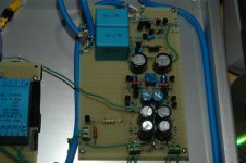
If you're still interested, I've drawn a pcb for the supply.
It can be downloaded here
It can be used as a single board, or as two separate boards,
just cut the pcb and implement the two five points connectors.
It accepts major brands of PCB mount transformers.
Use a 5VA transformer if you want to supply only one channel,
or use a 10VA one if you intend to supply two channels.
Cheers
Sigurd,
Yes your ckt is correct except below:
1. I use white follower at the output stage for the Jfet SE Pre-amp.
2. No Pot P1.
3. C4 & C6 use 150pF, too much high if without it.
4. Output use 10uF Rifa cap
5. Use lower supply voltage, +/-24V.
6. R3/R6 = 8.2k.
See photo attached.
Spencer
Yes your ckt is correct except below:
1. I use white follower at the output stage for the Jfet SE Pre-amp.
2. No Pot P1.
3. C4 & C6 use 150pF, too much high if without it.
4. Output use 10uF Rifa cap
5. Use lower supply voltage, +/-24V.
6. R3/R6 = 8.2k.
See photo attached.
Spencer
Attachments
Cheff,
1. The Aleph 1.7 lack of drive at low frequency in my system. 1.7 sound very soft, musical and never harch to me. Some valve fan may like it but I want a bit more bass and drive to my power amp.
2. UGS and Borbely pre has a output stage to drive and thus I get what I want.
3. I use Jfet i/v in my DAC and use same complementary jfet source follower and thus I think the drive to the preamp is ok.
Spencer
- Home
- Amplifiers
- Pass Labs
- UGS adventures