Hi
Listening test number 2.
I couldn’t wait till the potmeter was finished and start listening comparing against my previous posted Tube Preamp.
Starting with 150k feedback 15k input and 1k output to ground and this time Unbalanced in and Balanced out.
Still use a 50k alps at the input
The difference is very small between the 2 preamps with some favour of the tube pre for mids voices and in favour of the UGS module for top end bass and some more air overall.
Then I remove the 1k and change to 10k at the output to ground.
Man that’s like taking the handbrake of.
Much more dynamic more air and most important more musical.
Especially resolution is very good from bottom to top end.
Now it surpasses the tube pre easy.
Now the things I still want to try.
Find a solution for offset stability with priority to sound and maybe I have to make a compromise against balanced output difference.
Feedback resistors back to a gain of 5 and a different pot at the input.
My 7 bit ladder has a continue output impedance of 10k +/- 4 Ohms.
I like to use the output impedance of the potmeter as the input resistor for feedback.
What do you guys think of that?
Rob
Attachments
> Man that’s like taking the handbrake of.
A bit surprised to be honest.
Assuming you have a balanced power amp with say 20dB gain, the preamp output must be less than 0.2V, assuming normal listening levels. Which then means that the output stage is driving load current of 0.2mA with 7mA bias even with 1k load. And there is no shortage of bandwidth even with 1k Rout.
Using that as a reference, one should be using 350mA bias to drive 200ohm load ?? And that would be 34W dissipation for a balanced preamp with +/- 25V rails !!!!!
(I remember Borbely once said that his preamp can drive 150 ohm load as he advocates impedance loading of cables, and he uses 70mA bias. Maybe it has more to do with gain / transconductance than bias level ??)
Gets me thinking ........
(Maybe I should not try to look for a scientific explanation and just accept fact as is.)
Patrick
Hi Rob,
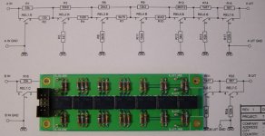
Nice pot and pcb")
I'm both pleased by your listening impressions, and, as Patrick,
a bit puzzled by the major change in sound between two resistors...
But, as Patrick also said, why should I not accept it ?
I'm currently finishing a second set of modules, so I'll be able quite soon
to directly swap modules (normally tomorrow). And the first comparison
will be between a 1K Rout and a 10K one
Anyway thanks for sharing, and keep us to date.
Cheers,
Nice pot and pcb
What do you guys think of that?
I'm both pleased by your listening impressions
, and, as Patrick,a bit puzzled by the major change in sound between two resistors...
But, as Patrick also said, why should I not accept it
?I'm currently finishing a second set of modules, so I'll be able quite soon
to directly swap modules (normally tomorrow). And the first comparison
will be between a 1K Rout and a 10K one
Anyway thanks for sharing, and keep us to date.
Cheers,
Hi
I can’t explain the difference between 10k and 1k.
But I build a lot of tube amps also with interstage transformers and always did listening test by load the transformer secondary with a resistor and I always remove the resistor because the sound was worse.
Now I’m using an Aleph with 8 output mosfets and feedback resistors are 100k and 10k so 20dB gain.
We did the listening with 2 people and I just place a 1k2 resistor parallel to the 10k resistor.
I remove the resistors 3 times and soldered them back.
The difference was big in my opinion and my friend says the same.
About the pot Cheff that’s why I was so interested in your setup and software.
Maybe I can learn something from it.
I have everything ready and the pot works but not yet test it in the preamp.
Did you already simulate your pot for in and output impedance?
And what about my previous question to place the pot into the feedback loop?
Rob
IR schematic and software?
Dear "Cheff",
Back in post #46 you mentioned,
" The µC is an Atmel AVR ATmega64. It's remote controlled (Philips
RC5 code), with a learn function. It is specifically designed to meet
my needs, but if needed, I will post the schematics, Gerber files and software. "
I'm looking to build an IR receiver with an Atmel AVR microprocessor. Is it still possible to obtain the schematic and software? Please!!!
Thank you,
Tommak
Rob, Cheff,
Care to do a little experiment for the 1k / 10k load ?
(I have not a running circuit and I am actually away from home right now.)
Leave the 10k at the output as Rob has it now, then add an additional (mocked-up) Curl follower (2SK170BL/2SJ74BL matched Idss around 7mA, +/- 15V Supply), and load the output of the buffer with 1k or 10k, and see if you hear a difference.
My theory is that the 1k is too much compared to the emitter resistor (750R) of the current mirror ouput BJT, but I might be totally wrong on this. The test should verify that. Of course I am not suggest that you leave the Follower on the circuit. Just looking for an explanation. (The curl follower has an apparently source resistor of around 20 ohm when used with no source degeneration.)
Patrick
Hi Rob,
Open loop gain.
Decreasing both values will decrease OL gain, so the CL gain...
Patrick, I'm afraid I don't see your point...
I'm not reluctant to test it, but I wonder if the test is really pertinent,
as the purpose of the Rout resistor won't be the same as a load for
the buffer than for the UGS...
As I see it (but it's only my way to explain) in the ugs, this Rout
resistor is mandatory, and not in the buffer : in the ugs, at idle, the
current sourced by the "upper" out bjt should be exacly the same
than the current sinked by the lower one. Thus no current runs to
ground through Rout, and the output offset is zero
Now when a signal is applied, the "upper" output current will differ from
the "lower" one (when one sources more, the other will automatically
sink less, and vice-versa). And the difference current will run through
Rout, and then will be converted to output voltage.
So in my mind, I see Rout more as an I/V converter than as a collector
load or whatever...
But may be it recudes to the same...
BTW, I'm finished with the second set of modules, with a 10K Rout.
No listening for the moment, but I performed DC stability verifications.
Obviously, the offset wanders a bit more than with the 1K resistors,
but I found that with heatsinking, it stays quite stable (under the mV)
So Rob, if you intend to keep the 10K, give a try to heatsinks, and
you won't have to use common mode feedback.
So more listening news soon
Cheers,
Rob Dingen said:Cheff
What’s the reason for the values of 1.5k and 750 Ohm?
Open loop gain.
Decreasing both values will decrease OL gain, so the CL gain...
Originally posted by EUVL
Rob, Cheff,
Care to do a little experiment for the 1k / 10k load ?
(I have not a running circuit and I am actually away from home right now.)
Leave the 10k at the output as Rob has it now, then add an additional (mocked-up) Curl follower (2SK170BL/2SJ74BL matched Idss around 7mA, +/- 15V Supply), and load the output of the buffer with 1k or 10k, and see if you hear a difference.
My theory is that the 1k is too much compared to the emitter resistor (750R) of the current mirror ouput BJT, but I might be totally wrong on this. The test should verify that. Of course I am not suggest that you leave the Follower on the circuit. Just looking for an explanation. (The curl follower has an apparently source resistor of around 20 ohm when used with no source degeneration.)
Patrick, I'm afraid I don't see your point...
I'm not reluctant to test it, but I wonder if the test is really pertinent
,as the purpose of the Rout resistor won't be the same as a load for
the buffer than for the UGS...
As I see it (but it's only my way to explain
) in the ugs, this Routresistor is mandatory, and not in the buffer : in the ugs, at idle, the
current sourced by the "upper" out bjt should be exacly the same
than the current sinked by the lower one. Thus no current runs to
ground through Rout, and the output offset is zero
Now when a signal is applied, the "upper" output current will differ from
the "lower" one (when one sources more, the other will automatically
sink less, and vice-versa). And the difference current will run through
Rout, and then will be converted to output voltage.
So in my mind, I see Rout more as an I/V converter than as a collector
load or whatever...
But may be it recudes to the same...
BTW, I'm finished with the second set of modules, with a 10K Rout.
No listening for the moment, but I performed DC stability verifications.
Obviously, the offset wanders a bit more than with the 1K resistors,
but I found that with heatsinking, it stays quite stable (under the mV)
So Rob, if you intend to keep the 10K, give a try to heatsinks, and
you won't have to use common mode feedback.
So more listening news soon
Cheers,
> I see Rout more as an I/V converter than as a collector
load or whatever...
I tend to agree with you that the experiment as proposed does not really serve the purpose of verifying any hypothesis.
The way I see it : is it not true that Rout / Re determines the gain of the second stage after the diff pair ? So the higher that ratio, the tighter the control of the feedback loop, and the less work the first stage has to do.
Maybe another question :
What would happen if you double the bias all over and half the 750R and also the 1k5.
That would be my guess.
Maybe some of the experts can help us with an explanation ??
Patrick
Hi Patrick,
Well, I guess we should make a difference between voltage gain and
current gain. The first stage would "normally" have a voltage gain
but we look after the drain current that is a reference for the current
current mirror, so the first stage "current" gain (Id/Vin) whould be
something like gm/(gm.Rs+1). The second stage current gain (Iout/Iin)
is roughly Rd/Re.
At this point, I assume we have a transconductance amp. And I'm not
quite sure of what happens after, i.e. the way to account for Rout here...
It's not the current variation through the collector of one output BJT
that creates the output voltage, like in a classical common emitter amp,
but rather the difference current between the two collector currents...
And the I/V conversion ration would be 1V/mA for a 1K resistor...
But maybe I overcomplicate things That would not be the first
time...
I'm by no mean an expert, but IMHO doubling the bias on the first stage
will only change the value of Fet's gm, but by a little amount. Thus the
"gain" of the first stage won't be changed much. Now if you half both
Rd and Re, the "gain" of the second stage won't change, as the ratio
of the mirrored currents would stay the same... So I do not think it will
change the OL gain.
But whether it changes the sound, that's another story
Cheers,
EUVL said:> I see Rout more as an I/V converter than as a collector
load or whatever...
I tend to agree with you that the experiment as proposed does not really serve the purpose of verifying any hypothesis.
The way I see it : is it not true that Rout / Re determines the gain of the second stage after the diff pair ? So the higher that ratio, the tighter the control of the feedback loop, and the less work the first stage has to do.
Well, I guess we should make a difference between voltage gain and
current gain
. The first stage would "normally" have a voltage gainbut we look after the drain current that is a reference for the current
current mirror, so the first stage "current" gain (Id/Vin) whould be
something like gm/(gm.Rs+1). The second stage current gain (Iout/Iin)
is roughly Rd/Re.
At this point, I assume we have a transconductance amp. And I'm not
quite sure of what happens after, i.e. the way to account for Rout here...
It's not the current variation through the collector of one output BJT
that creates the output voltage, like in a classical common emitter amp,
but rather the difference current between the two collector currents...
And the I/V conversion ration would be 1V/mA for a 1K resistor...
But maybe I overcomplicate things
That would not be the first time...
EUVL said:Maybe another question :
What would happen if you double the bias all over and half the 750R and also the 1k5.
That would be my guess.
Maybe some of the experts can help us with an explanation ??
Patrick
I'm by no mean an expert, but IMHO doubling the bias on the first stage
will only change the value of Fet's gm, but by a little amount. Thus the
"gain" of the first stage won't be changed much. Now if you half both
Rd and Re, the "gain" of the second stage won't change, as the ratio
of the mirrored currents would stay the same... So I do not think it will
change the OL gain.
But whether it changes the sound, that's another story
Cheers,
Cheff,
While I agree with you on your way of looking at the circuit as a transconductance amplifier, your closed-loop feedback is based on voltage. I think if you derive a formula for the open loop / closed loop voltage gain, you would find Rout in the formular.
The observation by Rob implies (in my interpretation) that a 10k Rout increases the open loop voltage gain by approx. a factor of 10 in comparison to 1k, and thus the feedback factor by also the same amount.
If this is correct, then one has to ask how much feedback the circuit has now with 1k Rout, and how one can increase the open loop gain while keep Rout at 1k (in case this is what one wants).
Again, my interpretation might not be correct.
Patrick
Hi Patrick,
The circuit without Rout is a transconductance amp, but including Rout
makes it a voltage amp. So the feedback loop is of course based on
voltage
I've tried to put it in equations, and if I'm not mistaken, the OL gain
(Differential out/Differential In) should be roughly something like :
G=2gm.Rd.Rout/(Re(1+gm.Rs))
where gm is the transconductance of a single fet (assuming all fets identical)
So obviously, increasing Rout increases OL gain by the same amount.
And it appears the only practical way of increasing the OL gain keeping
Rout constant is to increase the Rd/Re ratio...
I'm not sure of what you call feedback factor... If you take the classical
formula for feedback systems :
CLgain=G/(1+B.G)
where B is here Rin/Rfb and G the OL gain,
I know B.G as the loop gain, and (1+B.G) as the feedback amount...
Is the amount the factor ? Or the loop gain ?
CL gain sensivity is not high (1/(1+B.G)), so if the the OL gain (G) is
multipied by 10 (Rout from 1K to 10K), will increase the CL gain by
1.2 (according to Rob's feedback values 15K/150K). Just a little bit
more gain...
Speaking of that, I've made some listening tests swapping modules
with 1K Rout and 10K Rout.... I've taken care of volume adjustments
before successive listenings, to not be fooled by a louder volume
(higher gain) with the 10K loaded modules...
Well, I might be deaf as a leppard , but I didn't feel a difference...
I didn't find objective or immediate evidences as Rob did, either in
dynamics or in spatialisation... And I can't rely on subjective impressions
I may have felt, as I was equally inclined from time to time towards
one module, and towards the other one one record later... It was more
the records than the modules
But it raised interesting issues... My CL gain is quite low, so does a
higher gain bring some improvements ?
And most, I have a 10K pot at output... So it is in // with Rout...
With 1K Rout, it has a very small effect, but the total Rout is halved
whent i put 10K. So I must test a module without any Rout, and rely
on the pot to play this role. Will test
BTW, I wonder if Spencer could give a try to a 10K Rout. You have
the same configuration as Rob's : higher gain than me, pot at input.
Do you want to test and report ?
So many things, so little time...
Regards,
The circuit without Rout is a transconductance amp, but including Rout
makes it a voltage amp. So the feedback loop is of course based on
voltage
I've tried to put it in equations
, and if I'm not mistaken, the OL gain(Differential out/Differential In) should be roughly something like :
G=2gm.Rd.Rout/(Re(1+gm.Rs))
where gm is the transconductance of a single fet (assuming all fets identical)
So obviously, increasing Rout increases OL gain by the same amount.
And it appears the only practical way of increasing the OL gain keeping
Rout constant is to increase the Rd/Re ratio...
I'm not sure of what you call feedback factor... If you take the classical
formula for feedback systems :
CLgain=G/(1+B.G)
where B is here Rin/Rfb and G the OL gain,
I know B.G as the loop gain, and (1+B.G) as the feedback amount...
Is the amount the factor ? Or the loop gain ?
CL gain sensivity is not high (1/(1+B.G)), so if the the OL gain (G) is
multipied by 10 (Rout from 1K to 10K), will increase the CL gain by
1.2 (according to Rob's feedback values 15K/150K). Just a little bit
more gain...
Speaking of that, I've made some listening tests swapping modules
with 1K Rout and 10K Rout.... I've taken care of volume adjustments
before successive listenings, to not be fooled by a louder volume
(higher gain) with the 10K loaded modules...
Well, I might be deaf as a leppard
, but I didn't feel a difference... I didn't find objective or immediate evidences as Rob did, either in
dynamics or in spatialisation... And I can't rely on subjective impressions
I may have felt, as I was equally inclined from time to time towards
one module, and towards the other one one record later... It was more
the records than the modules
But it raised interesting issues... My CL gain is quite low, so does a
higher gain bring some improvements ?
And most, I have a 10K pot at output... So it is in // with Rout...
With 1K Rout, it has a very small effect, but the total Rout is halved
whent i put 10K. So I must test a module without any Rout, and rely
on the pot to play this role. Will test
BTW, I wonder if Spencer could give a try to a 10K Rout. You have
the same configuration as Rob's : higher gain than me, pot at input.
Do you want to test and report ?
So many things, so little time...
Regards,
Just forgot to mention...
Why use a volume pot at output in a classical way as a voltage divider ?
Rather use it to make Rout a variable resistor, and thus vary the gain.
Better use a switched resistors network, as a classical pot won't be
tightly matched enough...
Is it realistic ?
I'm gonna try soon, pretty straightforward to implement in my configuration...
Another journey begins
Cheers,
Why use a volume pot at output in a classical way as a voltage divider ?
Rather use it to make Rout a variable resistor, and thus vary the gain
. Better use a switched resistors network, as a classical pot won't be
tightly matched enough...
Is it realistic ?
I'm gonna try soon, pretty straightforward to implement in my configuration...
Another journey begins
Cheers,
I can't afford the time to run back through the thread and find the schematic, so I may be way out on a limb here...
The idea of adjusting the volume by varying the overall gain (instead of using a resistive divider at the input and/or output) comes up a couple of times per year--usually in the context of opamps, where it's easy to visualize.
Will it work?
Yes.
Is it a good idea?
Well...
Bear in mind that the distortion and distortion components will vary as the gain of the circuit is changed. In other words the circuit won't sound the same at all volumes. You'll find sweet spots perhaps, but then you'll also find other places where it sounds terrible.
Whether that suits you is another matter.
Grey
Hi Grey,
First post of the thread, second schematic
Yes, I know it comes up from time to time...
And that distortions figures may vary with the gain, although sims
- which I don't trust a lot, and it's an understatement - do not show
dramatic variations.
But here, the gain variation wouldn't be driven by the feedback amount,
contrary to op amps, and it may give different results...
So I won't know until I test it
Cheers
I can't afford the time to run back through the thread and find the schematic, so I may be way out on a limb here...
First post of the thread, second schematic
The idea of adjusting the volume by varying the overall gain (instead of using a resistive divider at the input and/or output) comes up a couple of times per year--usually in the context of opamps, where it's easy to visualize.
Will it work?
Yes.
Is it a good idea?
Well...
Bear in mind that the distortion and distortion components will vary as the gain of the circuit is changed. In other words the circuit won't sound the same at all volumes. You'll find sweet spots perhaps, but then you'll also find other places where it sounds terrible.
Whether that suits you is another matter.
Grey
Yes, I know it comes up from time to time...
And that distortions figures may vary with the gain, although sims
- which I don't trust a lot, and it's an understatement - do not show
dramatic variations.
But here, the gain variation wouldn't be driven by the feedback amount,
contrary to op amps, and it may give different results...
So I won't know until I test it
Cheers
CheffDeGaar said:Just forgot to mention...
Why use a volume pot at output in a classical way as a voltage divider ?
Rather use it to make Rout a variable resistor, and thus vary the gain
Better use a switched resistors network, as a classical pot won't be
tightly matched enough...
Is it realistic ?
Instead of increasing or decreasing the Rout, just have a 1 k pot as Rout, and pick the output voltage on the cursor of it. The overall gain remain the same (if connected to a high impedance device), but the output voltage vary.
Philippe
- Home
- Amplifiers
- Pass Labs
- UGS adventures