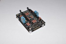
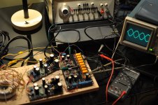
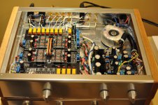
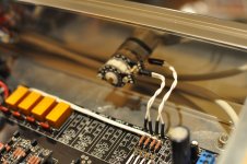
Here we go… The first photo shows a UGS module. The second one, a mother board with right and left UGS modules being tested. The third photo shows the complete preamp with two UGS in series for extra gain. It has been in use for years without a glitch. Knobs are: volume, input select, and phase reversal.
Perhaps NAR will kindly post photos of his build?
Perhaps NAR will kindly post photos of his build?
Attachments
Dual UGS in series configuration
Would be great if you could publish the details of the dual UGS in series configuration, I am in the process of building an UGS based preamp and could perhaps give a try.
Regards,
Alejandro
22.1K but the exact value is not critical. As you probably figured out already, the corresponding transistor controls a relay that shunts the unused IN- signal to ground when an unbalanced input is selected.
B.t.w. the UGS pre is well worth building. It did raise the transparency of my system. There was no turning back to the BLS, which is quite nice in its own right.
If anyone is interested in the UGS but need more gain, you can use two UGS in series. For volume control, wire a pot (10K) in shunt configuration between the + and - signals between the gain stages. As a side benefit, the input and output impedances then become volume-independent. I would be happy to provide details if anyone is interested. I've built it and it works nicely.
Pierre
Would be great if you could publish the details of the dual UGS in series configuration, I am in the process of building an UGS based preamp and could perhaps give a try.
Regards,
Alejandro
Alejandro
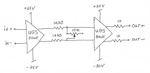
Yes, certainly. The diagram below shows one possible configuration.
Let's look at the volume control first. It is just a pot or step ladder that shunts the differential signal running from the front UGS to the back UGS. I had a nice 10k DACT handy, so this is the value that I used. In order to even out the attenuation steps, I put two resistors in series (1470 ohm) before the shunt. At the maximum volume setting, these cause 2.25 dB of attenuation. On the bright side, this configuration allows using a double-gang stepped attenuator in a balanced preamp.
This would work with UGS modules in stock form. But since I am a natural born experimenter, I tweaked the front and back modules a bit.
For the Front UGS, I changed RFB from 56K to 100K to increase the gain from 10 dB to 15 dB. Otherwise the module is stock.
For the Back UGS, you will note that I run higher supply voltages. To accommodate this without putting the precious jFets at risk, I increased the two 10k resistors biasing Q1, Q2, Q3, and Q4 from 10k to 15k. RFB is stock at 56K, so the gain is 10 dB. The preamp has been powered on for months in a closed enclosure without thermal issues.
The total gain of the preamp is thus 15 - 2.25 + 10 = 22.75 dB with balanced inputs and outputs. I like how it sounds with the F4. Hope this helps.
Pierre
Attachments
Last edited:
Dual UGS in series: Relative and absolute offset adjust
Pierre,
How do you adjust the relative and absolute offset?, with both UGS boards mounted in circuit or adjusting each UGS board alone.
Thanks for the info, I will try this configuration as soon as JFets and a Mouser order arrives.
Regards,
Alejandro
Pierre,
How do you adjust the relative and absolute offset?, with both UGS boards mounted in circuit or adjusting each UGS board alone.
Thanks for the info, I will try this configuration as soon as JFets and a Mouser order arrives.
Regards,
Alejandro
First I adjusted each UGS module alone - with its final, stabilized supply voltages. Then all together. Beware of cold drafts  .
.
I matched the Idss of the jFets as close as I could (within 0.4mA per module).
For testing each module, it helps at first to leave the RFBs out (unpopulated). Then it is possible to verify if all dc voltages are normal and if the transistors are biasing properly. There is a message in French by François (Flat) dated 11 January 2007 that explains this step by step. Found it on another forum long ago and all I have is a hard copy. After testing the module this way, I populated the RFBs and the modules worked without issues.
.I matched the Idss of the jFets as close as I could (within 0.4mA per module).
For testing each module, it helps at first to leave the RFBs out (unpopulated). Then it is possible to verify if all dc voltages are normal and if the transistors are biasing properly. There is a message in French by François (Flat) dated 11 January 2007 that explains this step by step. Found it on another forum long ago and all I have is a hard copy. After testing the module this way, I populated the RFBs and the modules worked without issues.
Thank you very much, I will follow your instructions when building my preamp.
I can't get matched N & P channel JFets, It was really difficult to me get the 2SK389BL and 2SJ109BL from trusted sources at a reasonable price, so I hope the offset can be adjusted propertly with the trims.
Regards,
Alejandro
I can't get matched N & P channel JFets, It was really difficult to me get the 2SK389BL and 2SJ109BL from trusted sources at a reasonable price, so I hope the offset can be adjusted propertly with the trims.
Regards,
Alejandro
It is a good idea to measure Idss (1) to know the value and (2) to verify if the jFet works. Match the best you can and let the trims do the rest. Keep us postedI can't get matched N & P channel JFets, It was really difficult to me get the 2SK389BL and 2SJ109BL from trusted sources at a reasonable price, so I hope the offset can be adjusted propertly with the trims.
.I wonder how close NAR and others were able to match their jFets? Did they find this to be necessary at all?
Last edited:


Thanks, I read most of the documents but in French. so only few I understand .
Since most of the builders has success on building this preamp, I will do the adjustment once it's in casing, cross my fingers on that one.
Ah the plastic can is a Toshiba thermal paste.
.Since most of the builders has success on building this preamp, I will do the adjustment once it's in casing, cross my fingers on that one
.Ah the plastic can is a Toshiba thermal paste.

Last edited:
I think it's V
Not knowing Idss, you can try the modules stock (as is).
If both n and p channels are V grade, and the devices have high Idss, then there will be more feedback than the modules were designed for. I don't know what the effect of more supersymmetry feedback would be (sonically or otherwise). I guess if your pre does sound or behave funny, then you can increase the Rfb from 56K to 100K to reduce the feedback and compensate for that extra gain from the jfets. Lowering feedback would increase the closed loop gain, which is nice because stock it is only 10 dB.
Pierre, the software programming it saying to use the ponyprog first before the Program. Can you confirm this? I'm lost there actually.
I'm using a crystalfontz LCD by the way.
Sorry, I used a different motherboard without any software or programming...
Not knowing Idss, you can try the modules stock (as is).
If both n and p channels are V grade, and the devices have high Idss, then there will be more feedback than the modules were designed for. I don't know what the effect of more supersymmetry feedback would be (sonically or otherwise). I guess if your pre does sound or behave funny, then you can increase the Rfb from 56K to 100K to reduce the feedback and compensate for that extra gain from the jfets. Lowering feedback would increase the closed loop gain, which is nice because stock it is only 10 dB.
Noted with thanks, I will post my progress and adjustment.
- Home
- Amplifiers
- Pass Labs
- UGS adventures