I'm in the middle of building the power supplies for the UGS preamp boards.
I bought J113s for the current source since I couldn't find J508s. I tested the Idss of the J113s and they seemed too high (15mA, 15mA, 18mA and 30mA - I bought four and they are Fairchild) Am I doing something wrong? Do folks have suggestions for a J508 or are the J113s OK?
I bought J113s for the current source since I couldn't find J508s. I tested the Idss of the J113s and they seemed too high (15mA, 15mA, 18mA and 30mA - I bought four and they are Fairchild) Am I doing something wrong? Do folks have suggestions for a J508 or are the J113s OK?
NYCOne, current through JFET (Id) is defined by voltage between the Gate and the Source (Vgs).
Id is highest when Vgs=0. Making the Source more positive than the gate lowers the Id.
So, to get the Id you want use the resistor connected to the Source. Resistor's value defines the voltage drop (Vgs) i.e. Id.
Id is highest when Vgs=0. Making the Source more positive than the gate lowers the Id.
So, to get the Id you want use the resistor connected to the Source. Resistor's value defines the voltage drop (Vgs) i.e. Id.
Juma-
I understand what you're saying.
My issue is:
I have a number of different transistors I can use - J113, K246, K170. I happen to have K246 that are the exact Idss called for (2.4mA). I would substitute them for the J113 called for in the BOM. Two issues: One is I am too inexperienced to know if the K246 are a good replacement (noise or other potential differences). Second, I was startled by the difference in measured Idss on the J113 compared to the data sheet (is it possible they are 15mA Idss when the data sheet claims 2mA)?
The thread is long and the sch. is buried somewhere in it - but since you plan to use the JFET as CCS, any of JFETs you mention will do the job (J508 is a JFET too) as long as your Id and Vds max. are OK (if noise is your concern use k170).
Don't worry about datasheet discrepancies - production tolerances can be wide...
Don't worry about datasheet discrepancies - production tolerances can be wide...
watch out
Hi,
Very recently I had the same struggle as you. I bought 10 Fairchild fets and they vary from 12-35mA. I think the 2mA is a minimum value in the datasheet.
There are another pitfalls. I don't know what PCB you have. But the integrated one with the relais isn't developped for a J113. On my PCB was a
2N5461 mentioned. As a J113 is a N-channel fet you have a new problem (2N5461 is a P-channel). There is also a difference in the pinning of the fets between Fairchild and other manufactorer so a lot of "fun" before you burn your fingers at the current source. With an Idss >20mA they are running really hot.
Tip of the day: use a 10k resistor as replacement to check the power supply first before you get started with jfet's.
Gr.
Johan
I'm in the middle of building the power supplies for the UGS preamp boards.
I bought J113s for the current source since I couldn't find J508s. I tested the Idss of the J113s and they seemed too high (15mA, 15mA, 18mA and 30mA - I bought four and they are Fairchild) Am I doing something wrong? Do folks have suggestions for a J508 or are the J113s OK?
Hi,
Very recently I had the same struggle as you. I bought 10 Fairchild fets and they vary from 12-35mA. I think the 2mA is a minimum value in the datasheet.
There are another pitfalls. I don't know what PCB you have. But the integrated one with the relais isn't developped for a J113. On my PCB was a
2N5461 mentioned. As a J113 is a N-channel fet you have a new problem (2N5461 is a P-channel). There is also a difference in the pinning of the fets between Fairchild and other manufactorer so a lot of "fun" before you burn your fingers at the current source. With an Idss >20mA they are running really hot.
Tip of the day: use a 10k resistor as replacement to check the power supply first before you get started with jfet's.
Gr.
Johan
I finally found that excellent thread after years spent stupidly trying to develop cable prototypes with no financial support ")
Well, that time was not lost for anything, for example, I learned many things about interconnects. I also got in touch with such nice person and so talented designer as is Allen Wright. So that's for cable ...
Now I'm in the redesign of my whole audio equipment. The Pearl II is a good base for LPs ... will get on a DAC soon, and for the preamp - yes, the UGS_V3 is on the tracks ... The power amps later
I currently re-design the pcb, to get better impregnation of the schematic itself. I retained the original board size, tracks and components placing. The most difficult thing will likely to find the 389 & 109 BL types ...
Thanks NP for his everlasting shine among the DIY community, and of course many thanks to François for his awesome work !!!
Regards,
nAr
Has anyone else tried Hifizen's version of the UGS circuit, with 2SA970s and 2SC2240s?
Chad mentioned the mids and highs were harsh. I'm tempted, but was wondering if there's a second opinion out there.
Chad mentioned the mids and highs were harsh. I'm tempted, but was wondering if there's a second opinion out there.
Schematic, as built...
The only thing not shown here is the 50R trimpot for differential offset trim, since this schemo was done for simulation purposes.
Last edited:
Has anyone else tried Hifizen's version of the UGS circuit, with 2SA970s and 2SC2240s?
I don't know of the use of 2SA970 and 2SC2240 in this particular circuit, but more than one thing is to consider for all UGS style build attempts:
The 2SK370BL in matched pair and the 2SJ108BL in matched pair too seem a like a very good replacement of the old K389BL/J109BL that are now obsolete.
Those devices have about same voltage max and currents, transconductance is about the same as the originals. With a tight IDSS matching it should work as good as the original double fets
Those devices seem to have slightly lower background noise than the K389/J109
The case itself is not a regular TO92, it's smaller so is better to achieve good thermal coupling between the devices, and even extent troublefree thermal coupling to the original ZTX parts
For this nice finding I credit 100% Dr. Kühnlein
Best regards,
nAr
Salut,
Hello,
My UGS is now a definitive prototype. Working out of the box
Many thanks to Mr PASS, many thanks to François,
many thanks to my friend Pierre without whom the build would never be possible,
and of course many thanks to the DIY audio community
Click on the pics to open them real size.
Build phase
UGS module detail
Overall view of the motherboard with the I/O assignment and signalisation
Fine tuning of the output offsets, inputs shorted. Cold, 1mV; once idle temp is reached, +/- 0,002 mV worst case.
Temp. of the heatsinks : mild 38 - 39 celsius
It's alive ....
Gain setting : RIN 15K RFB 100K to get sufficient gain with my unbal sources.
The motherboard automatically shuts minus input bus to ground in case an unbal source is selected.
For sound quality, I should let it open more
but from the very first notes, I can say it's an impressive authority
combined with a live sense of details Very lively
nAr
Hello,
My UGS is now a definitive prototype. Working out of the box
Many thanks to Mr PASS, many thanks to François,
many thanks to my friend Pierre without whom the build would never be possible,
and of course many thanks to the DIY audio community
Click on the pics to open them real size.
Build phase
An externally hosted image should be here but it was not working when we last tested it.
UGS module detail
An externally hosted image should be here but it was not working when we last tested it.
Overall view of the motherboard with the I/O assignment and signalisation
An externally hosted image should be here but it was not working when we last tested it.
Fine tuning of the output offsets, inputs shorted. Cold, 1mV; once idle temp is reached, +/- 0,002 mV worst case.
Temp. of the heatsinks : mild 38 - 39 celsius
An externally hosted image should be here but it was not working when we last tested it.
It's alive ....
An externally hosted image should be here but it was not working when we last tested it.
Gain setting : RIN 15K RFB 100K to get sufficient gain with my unbal sources.
The motherboard automatically shuts minus input bus to ground in case an unbal source is selected.
For sound quality, I should let it open more
but from the very first notes, I can say it's an impressive authority
combined with a live sense of details
Very lively nAr
Salut,
Hello,
My UGS is now a definitive prototype. Working out of the box
Many thanks to Mr PASS, many thanks to François,
many thanks to my friend Pierre without whom the build would never be possible,
and of course many thanks to the DIY audio community
Click on the pics to open them real size.
Build phase
UGS module detail
Overall view of the motherboard with the I/O assignment and signalisation
Fine tuning of the output offsets, inputs shorted. Cold, 1mV; once idle temp is reached, +/- 0,002 mV worst case.
Temp. of the heatsinks : mild 38 - 39 celsius
It's alive ....
Gain setting : RIN 15K RFB 100K to get sufficient gain with my unbal sources.
The motherboard automatically shuts minus input bus to ground in case an unbal source is selected.
For sound quality, I should let it open more
but from the very first notes, I can say it's an impressive authority
combined with a live sense of details
nAr
Very well done. What are you planning for a case?
I'm within a day or two of finishing my UGS preamp. I just have the power supplies and the UGS boards, not the whole preamp.
Did you use a JFET, a diode or a resistor on the optional spot of the power supply? I went with the resistor, I couldn't find a diode or JFET with the right current.
I also built a Borbely no feedback JFET preamp to compare head to head. I finished that last night. Spencer from these forums likes the Borbely better.
Very well done. What are you planning for a case?
I will use my old one from ZLS
one needs to move further It's hand made, all aluminumI'm within a day or two of finishing my UGS preamp. I just have the power supplies and the UGS boards, not the whole preamp.
Did you use a JFET, a diode or a resistor on the optional spot of the power supply? I went with the resistor, I couldn't find a diode or JFET with the right current.
I used a simple jfet. I used 2SK246Y grade from Selectronic. I just bought 10 of them, and could fine 2 pairs at about 2 - 2,4 mA
I also built a Borbely no feedback JFET preamp to compare head to head. I finished that last night. Spencer from these forums likes the Borbely better.
I didn't build the Borbely, but for sure it's a nice topology. For now I will let the UGS burn-in
nAr

yes. There's a big range in BL, is there a specific number that is recommended?
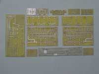
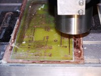
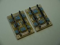
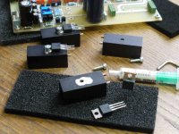
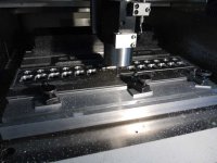
Good to read that some more fanatics have choosen this project. The UGS preamp is a very nicely and absolutely professionally developed and planned project, - thanks Francois! And thanks Manu for your support and encouragement! I have made my own boards, some were milled the rest was etched. Most stuffing and soldering is done already. Now I do the case and have started with the backplate. Here are a few pictures of my build.
Greetings to all, Martin
Greetings to all, Martin
Attachments
Last edited:
- Home
- Amplifiers
- Pass Labs
- UGS adventures