UGS mod1 - Worthwhile?
I added the "side-band" N-JFET circuit that Tino used to generate bias for the driver BJT's in his design. Here it is feeding the base of the cascoded current-mirror transistors. This circuit lets you dial in the NPN/PNP base voltages, though I'm not sure it has many other advantages. Would the current regulation of the JFET help any? Anyone care to comment on whether this addition is a waste of time and a few parts?
Thanks.
-willus
Attachments
what do you say would be the highest possible good sounding gain with this topo?Nelson Pass said:...and the "current mirror" version
more appropriate to high gain, high power.
thanks,
Rüdiger
Re: UGS mod1 - Worthwhile?
Hi Willus
I've seen - of course - Tino's design, but I've been so unlucky in the past
with folded cascodes (that simulated quite well) that I not tested it. Sorry...
But I really should take the step... No "folded" healing otherwise")
But the version I presented here is not cast in stone by no means.
Any improvements are welcome, and that's what this forum is about,
and why I posted it. So feel free to test it, only listening tests can tell
I'm both busy and lazy... But I'll test that next week, when I've
more time left...
And the heatsinks are home made, using aluminium profiles bought
in local hardware stores, cut to length, and drilled/tapped.
The pcbs are designed to provide about 15mm between the two
transistors rows, and it's the size of the "U" profile you can see on
photographs.
In Tino's design, the pot in the in the folded cascode biasing is used
to provide an adjustment for the absolute offset, but it would be
useless in "my" version...
IMHO (but I've not tested it), it won't have much influence on the
design. Perhaps some improvements in the PSRR, by making the
cascode bias voltage more immune to supply variations...
You could also lower the three divider resistors (keeping the same
ratio) to increase the current through the divider. Thus, the current
drawn by the cascoding BJTs will have less impact on the bias
voltage.
Another thing to test
Regards
Hi Willus
z_willus_d said:Hello All,
I'm curious if anyone has considered Tino's UGS circuit (see my rendering below or the orignal thread here: http://www.diyaudio.com/forums/showthread.php?s=&threadid=54826&perpage=10&pagenumber=16)
It's simulated well. It uses complimentary differential folded cascode with the JFETs. Seems to get slightly better THD with my simulator for what that's worth. I'm still more inclinded toward Cheff's UGS. as it's been built and tested, but Mr. Pass seemed to give the nod to Tino's rendition. (He mentioned that the design improved "for him" with CCS in place of the 200-ohm drain resistors.) Also, I think the way Tino provides "knobs" to set the base voltages using another JFET and pot could have it's benefits. Could something like this work in Cheff's design for improved control? Well, just wondering what others think about Tino's design. The X2_ugs3,4 thread kind of just died about a year ago and nothing more was said since about Tino's design, though it seemed promising.
I've seen - of course - Tino's design, but I've been so unlucky in the past
with folded cascodes (that simulated quite well) that I not tested it. Sorry...
But I really should take the step... No "folded" healing otherwise
But the version I presented here is not cast in stone by no means.
Any improvements are welcome, and that's what this forum is about,
and why I posted it. So feel free to test it, only listening tests can tell
Cheff, did you ever get a chance to play with the different BJT currents? Can you tell me where you obtained your heatsink structure(s) for the UGS?
I'm both busy and lazy... But I'll test that next week, when I've
more time left...
And the heatsinks are home made, using aluminium profiles bought
in local hardware stores, cut to length, and drilled/tapped.
The pcbs are designed to provide about 15mm between the two
transistors rows, and it's the size of the "U" profile you can see on
photographs.
I added the "side-band" N-JFET circuit that Tino used to generate bias for the driver BJT's in his design. Here it is feeding the base of the cascoded current-mirror transistors. This circuit lets you dial in the NPN/PNP base voltages, though I'm not sure it has many other advantages. Would the current regulation of the JFET help any? Anyone care to comment on whether this addition is a waste of time and a few parts?
In Tino's design, the pot in the in the folded cascode biasing is used
to provide an adjustment for the absolute offset, but it would be
useless in "my" version...
IMHO (but I've not tested it), it won't have much influence on the
design. Perhaps some improvements in the PSRR, by making the
cascode bias voltage more immune to supply variations...
You could also lower the three divider resistors (keeping the same
ratio) to increase the current through the divider. Thus, the current
drawn by the cascoding BJTs will have less impact on the bias
voltage.
Another thing to test
Regards
All,
I source my 2SA970/2SC2240GR in Shenzhen, China electronics market. It is just about 1.5 hrs travel from Hong Kong. A970 and C2240 is cheap at about US$0.1 per pc for 200 pcs bag (MOQ).
For K389, I get the last 30 pcs from a HK electronic hobby shop. For the J109, I get it from a friend in Singapore. I happen to visit Singapore once a month and there is stocker keeping some of these J109GR. Price of the J109 is about US$3-4 while the K389 is only $1.5 to me.
I ever try HKinventory.com but some of the quotes are very expensive at $4.5 to $6 per pc from US and I have to pay the postage fee also.
Regards,
> I source my 2SA970/2SC2240GR in Shenzhen
My only concern for Shenzhen would be whether they are original Toshiba's or fakes.
I have seen enough Toshiba fakes.
> Price of the J109 is about US$3-4 while the K389 is only $1.5 to me.
This is fair price. J109 has always been more expensive than K389. Do they still have J109BLs or J109Vs ?
Patrick
Hi
I build exactly like your schematics and did some measurements.
Only my power supply = +/- 21V and I use BC550 and BC560.
Gain SE in and Out 1.65
Gain SE in and Bal out 3.3
Bandwidth 760Khz -3dB
There is no overshoot.
Max amplitude SE = 20Vpp and Bal 40Vpp.
Distortion measurement is difficult because its balanced out and I don't have tools for that.
But when I measure one side its below 0,01% and second harmonics so Balanced should be lower because it cancel 2e harmonics.
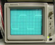
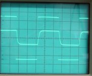
I attach a picture from my scope with a square wave at 100Khz
I build exactly like your schematics and did some measurements.
Only my power supply = +/- 21V and I use BC550 and BC560.
Gain SE in and Out 1.65
Gain SE in and Bal out 3.3
Bandwidth 760Khz -3dB
There is no overshoot.
Max amplitude SE = 20Vpp and Bal 40Vpp.
Distortion measurement is difficult because its balanced out and I don't have tools for that.
But when I measure one side its below 0,01% and second harmonics so Balanced should be lower because it cancel 2e harmonics.
I attach a picture from my scope with a square wave at 100Khz
Attachments
Onvinyl said:what do you say would be the highest possible good sounding gain with this topo?
I have gotten as high as 80 dB open loop without special
effort (or load), but the quality is much dependent on the
application.
Hi Rob,
Wow !
How quick, and what a nice job !
Concerning your supply, is it the schematic I posted ?
What about the DC offset ? Did you measure the bias of each stage ?
I'm a bit surprised by the max output amplitude, pretty close to the rail
But I only simulated it, and have no measurements, my signal generator
output not being high enough for the gain I chose...
But these are globally nice figures, IMHO at least
Do you happen to have a "real" distortion meter ?
Do you have a picture of the direct signal from your generator corresponding
to the USG output signal (100kHz square wave) ? Just to see if the
transitions are really rounded by the UGS... My generator begins to
exhibit some weakness after 20kHz (DIY...), so I really can't tell about
the HF behavior... But given the BW you measured, I think I should
blame it on the UGS (1/7th of the BW @ 100kHz), and not on the generator...
Again, nice and neat job.
Quite eager to read your listening impressions
Balanced or unbalanced ?
How did you measure it ? I just have some doubts on the method for
assesing it... First sims I did gave around 500 Ohms, but I not so sure now.
Each method I chose gives different results... I'll have to try to get it
through the circuit equations... When I have time
Anyway, thanks for trying it, and for the measurements you made.
When do you think you can report back your listening impressions ?
Regards
Rob Dingen said:Hi
I build exactly like your schematics and did some measurements.
Only my power supply = +/- 21V and I use BC550 and BC560.
Gain SE in and Out 1.65
Gain SE in and Bal out 3.3
Bandwidth 760Khz -3dB
There is no overshoot.
Max amplitude SE = 20Vpp and Bal 40Vpp.
Distortion measurement is difficult because its balanced out and I don't have tools for that.
But when I measure one side its below 0,01% and second harmonics so Balanced should be lower because it cancel 2e harmonics.
I attach a picture from my scope with a square wave at 100Khz
Wow !
How quick, and what a nice job !
Concerning your supply, is it the schematic I posted ?
What about the DC offset ? Did you measure the bias of each stage ?
I'm a bit surprised by the max output amplitude, pretty close to the rail
But I only simulated it, and have no measurements, my signal generator
output not being high enough for the gain I chose...
But these are globally nice figures, IMHO at least
Do you happen to have a "real" distortion meter ?
Do you have a picture of the direct signal from your generator corresponding
to the USG output signal (100kHz square wave) ? Just to see if the
transitions are really rounded by the UGS... My generator begins to
exhibit some weakness after 20kHz (DIY...), so I really can't tell about
the HF behavior... But given the BW you measured, I think I should
blame it on the UGS (1/7th of the BW @ 100kHz), and not on the generator...
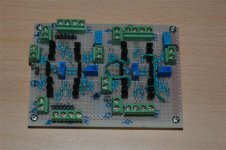
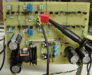
And the picture of my board.
I only build one half.
Now I finish it and do some listening.
Again, nice and neat job.
Quite eager to read your listening impressions
Forgot to tell.
The output impedance is 230 Ohm.
Balanced or unbalanced ?
How did you measure it ? I just have some doubts on the method for
assesing it... First sims I did gave around 500 Ohms, but I not so sure now.
Each method I chose gives different results... I'll have to try to get it
through the circuit equations... When I have time
Anyway, thanks for trying it, and for the measurements you made.
When do you think you can report back your listening impressions ?
Regards
Output Impedance
Rob, et al., I too would be interested in the method used to determine output impedance. Cheff, how did you simulate it? Output into a known impedance with pass on frequency looking for attenuation? SE is twice the imp of BAL right?
Cheff, as for lowering the value Ratio on the resistors in my attempt at adding Tino’s BJT bias circuit, that doesn't work for me. With the current values I simulate ~4.5mA through the JFET and the Vgs is ~0V. I did note in the 2sk170 datasheet that a Vgs of -400mV gives a better/flatter Ids curve, but I wasn’t able to obtain the correct 10V/-10V split with that Vgs. Lowering the resistor value ratio for higher currents threw off the balance of the voltage divider. Nevertheless, isn't 4.5mA through the JFET nearly ideal? That should be more than enough to overwhelm the minor Base currents in the uA range, right? I agree that this CS adds little benefit other than PSRR, but it did seem to help balance the base-voltages, whereas with the simple resistor divider I get a slight imbalance of base bias voltage between the NPN and PNP transistor nodes.
I’m still waiting on the transistors to build a test board. Fairchild’s sample system/website is the worst, slowest, and most useless (or user-friendly-less) system I’ve encountered in the industry.
Patirck,
Yes, I cannot know whether they are real or fake but at this price, there is no point for people to clone it. Actually in Singapore I only pay $0.08 for A970BL (higher hfe part) which is even cheaper than Shenzhen but the Singapore distributor did not carry any C2240. I check all the hfe and they are within spec. Is there a way to check whether they are fake?
So far I used some 2SK170BL from Shenzhen and I do not see any difference from those I get if from Singapore distributor. I did experience some fake IRF610 or IRF9610 before and at the end I have to buy from Singapore distributor which is at a bit higher price.
Jacco, thank you for your offer but I do not need more J109 at this moment. I hv 10 pcs more and is enough for me to build one more pre-amp.
Cheers
> Is there a way to check whether they are fake?
You can run some current through with a function generator (triangular wave), measure base and collector current using an oscilloscope, and plot channel 1 vs ch 2. The slope gives you hfe, and you can see how constant hfe is with Ic.
The curve for fakes (that I measured) are not linear.
Patrick
You can run some current through with a function generator (triangular wave), measure base and collector current using an oscilloscope, and plot channel 1 vs ch 2. The slope gives you hfe, and you can see how constant hfe is with Ic.
The curve for fakes (that I measured) are not linear.
Patrick
Hi Cheff
I build the same powersupply.
Bias jfet is about 3.8ma and output 7.6ma
And that bias with 1k to ground and you got the output swing
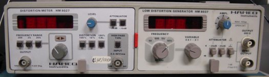
I have a distorsion analizer from Hameg not very hightech but good enough and distorsion is also at output to look at it on a scope.
Rob
I build the same powersupply.
Bias jfet is about 3.8ma and output 7.6ma
And that bias with 1k to ground and you got the output swing
I have a distorsion analizer from Hameg not very hightech but good enough and distorsion is also at output to look at it on a scope.
Rob
Attachments
I attach a picture from the scope with 100Khz signal output and input.
The output impededance is measured with a 1K resistor between + and - output.
Input is - input to ground.
Then I take a thru RMS meter put 4 volt ac to the output of the preamp and then short it with the 1k resistor.
With the difference between the to value you can calculate the output impedance.
I hope to setup a listening test on Monday evening.
Rob
Attachments
Re: Output Impedance
Unbalanced output impedance is half the balanced one.
On simulation with Cheff's UGS, I have 125 Ohms unbalanced (between out+ or out- and Ground) and 250 Ohms balanced (between out+ and out-).
Philippe
SE is twice the imp of BAL right?
Unbalanced output impedance is half the balanced one.
On simulation with Cheff's UGS, I have 125 Ohms unbalanced (between out+ or out- and Ground) and 250 Ohms balanced (between out+ and out-).
Philippe
Hi Rob,
the suplly voltage to 21 V ?
If my math is ok, the measured distortion of
less than 0.01% gives less than -80dB, and that's the simulated range.
Thanks for the picture.
I should have remember Thevenin's theorem Shame on me
A variation on the (open circuit voltage/short circuit current) classical
formula
I just tried it with the simulator, and it gives 233Ohms balanced,
and 116.5 Ohms unbalanced. Quite impressive to achieve such a
great agreement with measurements ! Even the gain figures are
the same you have (3.3 balanced). Too good to be true
I just can't wait
Thanks for all the clarifications, and happy building.
Regards
OK. You use a different transformer, or is it a choice of yours to limitI build the same powersupply.
the suplly voltage to 21 V ?
As expectedBias jfet is about 3.8ma and output 7.6ma
I wish I have this oneI have a distorsion analizer from Hameg not very hightech but good enough and distorsion is also at output to look at it on a scope.
If my math is ok, the measured distortion ofless than 0.01% gives less than -80dB, and that's the simulated range.
So I was right to blame it on the UGSI attach a picture from the scope with 100Khz signal output and input.
Thanks for the picture. The output impededance is measured with a 1K resistor between + and - output.
Input is - input to ground.
Then I take a thru RMS meter put 4 volt ac to the output of the preamp and then short it with the 1k resistor.
With the difference between the to value you can calculate the output impedance.
I should have remember Thevenin's theorem
Shame on me A variation on the (open circuit voltage/short circuit current) classical
formula
I just tried it with the simulator, and it gives 233Ohms balanced,
and 116.5 Ohms unbalanced. Quite impressive to achieve such a
great agreement with measurements ! Even the gain figures are
the same you have (3.3 balanced). Too good to be true
I hope to setup a listening test on Monday evening.
Rob
I just can't wait
Thanks for all the clarifications, and happy building.
Regards
- Home
- Amplifiers
- Pass Labs
- UGS adventures