Hi Cheff,
Very nice work and I am interested to build your current mirror UGS. Few questions:
1. The Idss of K389 and J109 BL grade is from about 6mA and up to 12mA, since the bias is at about 3.5mA, can I use fet of about 6.5mA Idss? What is the performance difference (gain, distortion, sound etc.) for 6.5mA and 10mA Idss parts?
2. Must I match the Idss of K389 to J109, or within what % will not deteriate the distortion/gain too much?
The reason I ask is that I have about 20pcs K389 but no J109 and if I am to get J109 to match them, I have to know how many expensive J109 I should buy.
Where do you think J109 is still available?
Thanks,
Spencer
Cheff,
Nice pre.
It's the UGS that puzzles me a little bit.
You mentioned a biascurrent through the jfets of 3,5mA.
The current mirror would mirror this bias current to the output bjt.
But it looks like the current through the output (being part of the
mirror) is much higher?
Is the mirror not functioning as a mirror?
Also OL gain looks like 25-26 dB. CL gain 14dB
That's awfull liitle feedback")
But then you mention 35dB as OL Gain.
Just to verify: Could you post the bias voltages for the jfets.
The results I get (in sim using simetrix) are very similar to one of
the previous posters. Notice the crossover distortion?
Hope you can shed a light or two...
Regards
Nice pre.
It's the UGS that puzzles me a little bit.
You mentioned a biascurrent through the jfets of 3,5mA.
The current mirror would mirror this bias current to the output bjt.
But it looks like the current through the output (being part of the
mirror) is much higher?
Is the mirror not functioning as a mirror?
Also OL gain looks like 25-26 dB. CL gain 14dB
That's awfull liitle feedback
But then you mention 35dB as OL Gain.
Just to verify: Could you post the bias voltages for the jfets.
The results I get (in sim using simetrix) are very similar to one of
the previous posters. Notice the crossover distortion?
Hope you can shed a light or two...
Regards
Hi all,
Thanks for the questions
Bias will depend on the Idss ratings, since it impacts on the Id=f(vgs) curve.
I quickly simulated using GR parts, with an Idss of about 4mA, and
as awaited the bias is lower (2.3mA). The whole pre will work, but
expect lower gain, both open loop and with CR. So, to answer your
question, it will work for a 6.5mA part, but the input range before
clipping will be reduced, and hence the output swing. But in
"normal" applications, the clipping levels will seldom be reached...
So if you find BL parts, just try them, listen carefully on your setup,
and try to go ahead by matching Idss, pinchoff, transconductance,
Vbe, Hfe, etc... and tell us what you find. That's what this forum is
about
The fets I used are not matched (N & P wise) but their Idss is between
8 and 10mA each, for those I measured. And I didn't tried to match
them, but your point is an interesting issue. I don't have the
proper measurement facilities, so it's very hard for me to tell you
about real distorsion figures... But sure, this has to be investigated.
Again, buy 2 to 4 2SJ109BL, and try them the design before going
further... In the case you don't like it...
I really don't know. Got mine in France. But in your part of the world,
this should be easier. Had a look at http://www.hkinventory.com/public/Home.asp ?
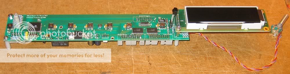
Thanks Patrick.
The control board is also my design, but the final pcb was a bit
beyond my local shop possibilities, so I had it made by a pro shop,
which explains the different color
The µC is an Atmel AVR ATmega64. It's remote controlled (Philips
RC5 code), with a learn function. It is specifically designed to meet
my needs, but if needed, I will post the schematics, Gerber files and
software.
A view of the whole board :
Well, it's an "amplifying" mirror
Just a crumb from the master :
http://www.diyaudio.com/forums/showthread.php?postid=720295#post720295
It depends on which gain you're talking about, and I generally
consider the differential gain (Vout+ - Vout-)/(Vin+ - Vin-). My sims
give an OL Diff Gain of 33dB (sorry for the 35dB, it was from memory....),
and a CL Gain of 10.5dB. Substract 6dB to get the unbalanced gain.
Besides, it seems to me that NP mentionned that SuSy was more
effective when the amount of feedback was not too high, but
I can't find the post...
Here you are (bias conditions):
I'm a bit puzzled about your crossover distortion, as both branches
(positive and negative) are always working and never cutting off..
Do we speak about the same thing ?
Regards,
Thanks for the questions
spencer said:1. The Idss of K389 and J109 BL grade is from about 6mA and up to 12mA, since the bias is at about 3.5mA, can I use fet of about 6.5mA Idss? What is the performance difference (gain, distortion, sound etc.) for 6.5mA and 10mA Idss parts?
Bias will depend on the Idss ratings, since it impacts on the Id=f(vgs) curve.
I quickly simulated using GR parts, with an Idss of about 4mA, and
as awaited the bias is lower (2.3mA). The whole pre will work, but
expect lower gain, both open loop and with CR. So, to answer your
question, it will work for a 6.5mA part, but the input range before
clipping will be reduced, and hence the output swing. But in
"normal" applications, the clipping levels will seldom be reached...
So if you find BL parts, just try them, listen carefully on your setup,
and try to go ahead by matching Idss, pinchoff, transconductance,
Vbe, Hfe, etc... and tell us what you find. That's what this forum is
about
spencer said:2. Must I match the Idss of K389 to J109, or within what % will not deteriate the distortion/gain too much?
The reason I ask is that I have about 20pcs K389 but no J109 and if I am to get J109 to match them, I have to know how many expensive J109 I should buy.
The fets I used are not matched (N & P wise) but their Idss is between
8 and 10mA each, for those I measured. And I didn't tried to match
them, but your point is an interesting issue. I don't have the
proper measurement facilities, so it's very hard for me to tell you
about real distorsion figures... But sure, this has to be investigated.
Again, buy 2 to 4 2SJ109BL, and try them the design before going
further... In the case you don't like it...
spencer said:Where do you think J109 is still available?
I really don't know. Got mine in France. But in your part of the world,
this should be easier. Had a look at http://www.hkinventory.com/public/Home.asp ?
EUVL said:Cheff,
Very impressive.
Could you tell us a bit about your control board ?
Is it your own design (as a see a different PCB colour to the rest) ?
I guess it is uP based, with remote control ?
What uP are you using ?
Thanks,
Patrick
Thanks Patrick.
The control board is also my design, but the final pcb was a bit
beyond my local shop possibilities, so I had it made by a pro shop,
which explains the different color
The µC is an Atmel AVR ATmega64. It's remote controlled (Philips
RC5 code), with a learn function. It is specifically designed to meet
my needs, but if needed, I will post the schematics, Gerber files and
software.
A view of the whole board :
rtirion said:It's the UGS that puzzles me a little bit.
You mentioned a biascurrent through the jfets of 3,5mA.
The current mirror would mirror this bias current to the output bjt.
But it looks like the current through the output (being part of the
mirror) is much higher?
Is the mirror not functioning as a mirror?
Well, it's an "amplifying" mirror
Just a crumb from the master :
http://www.diyaudio.com/forums/showthread.php?postid=720295#post720295
rtirion said:Also OL gain looks like 25-26 dB. CL gain 14dB
That's awfull liitle feedback
But then you mention 35dB as OL Gain.
It depends on which gain you're talking about, and I generally
consider the differential gain (Vout+ - Vout-)/(Vin+ - Vin-). My sims
give an OL Diff Gain of 33dB (sorry for the 35dB, it was from memory....),
and a CL Gain of 10.5dB. Substract 6dB to get the unbalanced gain.
Besides, it seems to me that NP mentionned that SuSy was more
effective when the amount of feedback was not too high, but
I can't find the post...
rtirion said:Just to verify: Could you post the bias voltages for the jfets.
Here you are (bias conditions):
rtirion said:The results I get (in sim using simetrix) are very similar to one of
the previous posters. Notice the crossover distortion?
I'm a bit puzzled about your crossover distortion, as both branches
(positive and negative) are always working and never cutting off..
Do we speak about the same thing ?
Regards,
For people having downloaded the PCBs' PDF, there's a little error on the actual
size of the boards. The correct size is 55.12mm x 38.34 mm. You can use the pdf
you already have "as is", but don't try to scale it to get the size mentionned in the
file
The pdf has been corrected, and is still available here
Sorry for inconvenience
Regards
size of the boards. The correct size is 55.12mm x 38.34 mm. You can use the pdf
you already have "as is", but don't try to scale it to get the size mentionned in the
file
The pdf has been corrected, and is still available here
Sorry for inconvenience
Regards
Problem solved.
Cheff,
You're a live safer.
The schematic with the bias voltages was very, very helpfull.
Showed I made a terrible mistake. Used a j175 model instead
of 2sj109 model.
That tipped things a little out of balance.
Checked the schematic more than 10 times, still didn't see my
mistake. I am probably a seeing blind bat or something.
Unfortunatly I do no longer own a huge CRT monitor.
Otherwise I would show you the big dents in the screen from
banging my head against it.
But, I changed the j175 to 2sj109 and everything (bias wise and
looking at the wavevorm 1K sine, no more crossover) looks perfectly normal.
Bias voltages/currents are a little different but nothing alarming.
Will look at OL and CL gain, and report back later.
Thanks again
Hi Cheff
I'm very intrested would you post it.
Looks very nice.
Thanks
Rob
The µC is an Atmel AVR ATmega64. It's remote controlled (Philips
RC5 code), with a learn function. It is specifically designed to meet
my needs, but if needed, I will post the schematics, Gerber files and
software.
I'm very intrested would you post it.
Looks very nice.
Thanks
Rob
Rob Dingen said:Hi Cheff
I'm very intrested would you post it.
Looks very nice.
Thanks
Rob
Hi Rob,
Well, I'll need a little time to clean up drawings and check all.
A week or two, I think, but I'll post it.
courage said:Hello Cheff,
Nice work, very impressive. Hats off.
Simulation figures look good. To what extend do they correlate with real measured figures?
Regards.
Hi courage,
Thanks for kind words
Well, difficult to say.
1) Sims use models, and to what extent models are faithful....
2) I do not have pro measurement gear... The only measurements
were preformed using a PC soundcard
And softwares used give little differences in results
Nevertheless, you'll find some figures in this thread
If I remember correctly, when measuring THD with a PC, H2 was -80dB
and H3 even less...
Cheff,
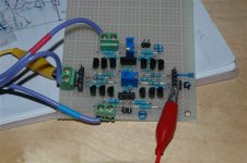
I have tried out in a board on your UGS ver3 circuit - current mirror and the dc bias and offset is very stable. Output offset is within +/-0.5mV for both balance and single end output to ground. The K389 and J109 current is at about 2.9mA and the last output bjt mirror is at 5.8mA which is very stable from power on till 30 mins warmup.
BJT to use are : 2SA970GR / 2SC2240GR with gain 220 / 250 on average. I did not match them closely as I know the batch is within +/- 20 in hfe.
Idss for K389BL is 6.5mA while J109GR is at 6.2mA. This is the reason that I get only 2.9mA bias current per fet and is very close to your estimation and simulation.
This is just a evaluation board for me and I am yet to test the output and input offset, frequency response using my sig gen and scope. Sorry I have no distortion meter!
By the way, where you get your sound card and software for distortion measurement and can I know what is the cost of hardware and software in total?
Regards,
Spencer
Attachments
spencer said:This is just a evaluation board for me and I am yet to test the output and input offset, frequency response using my sig gen and scope. Sorry I have no distortion meter!
[/B]
Hi, I'm lurking in the background and can't wait for more measurementsd and sound impressions.
Could I get by with BC550/560 replacing the zetex parts?
Rüdiger
Hi Spencer,
Very nice job. Congrats !
BTW, you must be one a the few that were bold enough to mount
dual jFets on perf boards. Kudos !
Glad you could achieve such good offset figures without any problems
Did you see any variations in offset with temperature ? Without
heatsinking, it was wandering a bit too much for my taste, but as
your bias is a little lower than mine, may be the heatsinking is not
that necessary.
Speaking of your lower bias, I do not think it will raise problems
(both in distortion and clipping limit) at normal listening levels
Please post your measurement results for bandwidth, I do not have a
proper sig gen for measuring it. And test it on square waves, just to
see if you have overshoot on transitions. It's quite implementation
dependent, so don't be disappointed if you see nothing
The software I use is RMAA (Right Mark Audio Analyzer), freely avalaible
at http://www.rightmark.org . My sound card is a mere and cheap SB
Live 5.1, with nothing fancy. I'm totally new at using this software, so I
must dig a little to get more accurate results.
So keep it up, and when your finished with tests, please post your
listening impressions
Again, great job
Onvinyl said:Could I get by with BC550/560 replacing the zetex parts?
Rüdiger [/B]
No problemo
The "historical" reason for using zetex parts was their form factor
which allowed a more efficient thermal coupling with my "heatsinks",
and their thickness that is close to the Toshiba's.
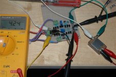
Cheff,
I use 47k for Rfb and 10k for Rin and supply voltage about +/-22.7V
I have some measurement result as below:
1. Gain: SE to SE is 2 times with the other input shorted to ground. If the other input is not grounded, the gain is 1.
SE to BAL gain is 4 times with one input grounded.
Bal to Bal gain is also 4 times.
2. Freq response: This is more difficult to measure as I dont have bal input in my scope but I use a audio transformer to couple the sig gen as a bal input to the UGS. -3db is at about 1MHZ and with input transformer is about 50KHz (limited by the input audio transformer).
3. Square wave: Do not see much over shoot at up to 100kHz. At below 500Hz, ther is a bit tilt upward at the starting of the step. I am not too sure if it is due to my sig gen output capacitor or not. No ringing at all.
4. Drift: Yes there is drift but the adjustment for bal out can be down to below 0.3mV and SE out can be down to 1mV. I use my finger to touch two of output bjts to get worst drift due to variation of heat dissipation. The result is that Bal drift is about 6mV and the SE out to ground is about 12mV. Lastly I use my hot air gun to heat up the whole pcb to about 50 deg C and the drift from Bal out or SE to gound is about the same at below 1mV. So my conclusion is to make sure the whole board is put inside a close enclosure with no air vantilation. NP put the board reverse and have the Pots on top for final adjustment should be sufficient for my application.
Regards,
Spencer Cheung
Attachments
Hi Spencer,
You could measure it simply by shorting one input to ground and
taking indifferently one output or the other... Won't have a great
impact on the BW making it work as a unbal to bal converter
Could you DC couple your signal generator and scope ?
I haven't seen this LF tilt. Just clean square signals...
Yep. That's the thermal unbalance between each quadrant of the circuit
that causes drifts... If all is equally heated, all the properties should
move together and limit drifts. That why I used small heatsinks,
but if you can live with these small variations, that's nice
So keep us informed of your progress, most of all when you will have
listened to the babies...
Regards,
spencer said:Cheff,
2. Freq response: This is more difficult to measure as I dont have bal input in my scope but I use a audio transformer to couple the sig gen as a bal input to the UGS. -3db is at about 1MHZ and with input transformer is about 50KHz (limited by the input audio transformer).
You could measure it simply by shorting one input to ground and
taking indifferently one output or the other... Won't have a great
impact on the BW making it work as a unbal to bal converter
3. Square wave: Do not see much over shoot at up to 100kHz. At below 500Hz, ther is a bit tilt upward at the starting of the step. I am not too sure if it is due to my sig gen output capacitor or not. No ringing at all.
Could you DC couple your signal generator and scope ?
I haven't seen this LF tilt. Just clean square signals...
4. Drift: Yes there is drift but the adjustment for bal out can be down to below 0.3mV and SE out can be down to 1mV. I use my finger to touch two of output bjts to get worst drift due to variation of heat dissipation. The result is that Bal drift is about 6mV and the SE out to ground is about 12mV. Lastly I use my hot air gun to heat up the whole pcb to about 50 deg C and the drift from Bal out or SE to gound is about the same at below 1mV. So my conclusion is to make sure the whole board is put inside a close enclosure with no air vantilation. NP put the board reverse and have the Pots on top for final adjustment should be sufficient for my application.
Yep. That's the thermal unbalance between each quadrant of the circuit
that causes drifts... If all is equally heated, all the properties should
move together and limit drifts. That why I used small heatsinks,
but if you can live with these small variations, that's nice
So keep us informed of your progress, most of all when you will have
listened to the babies...
Regards,
What about Tino's UGS
Hello All,
I'm curious if anyone has considered Tino's UGS circuit (see my rendering below or the orignal thread here: http://www.diyaudio.com/forums/showthread.php?s=&threadid=54826&perpage=10&pagenumber=16)
It's simulated well. It uses complimentary differential folded cascode with the JFETs. Seems to get slightly better THD with my simulator for what that's worth. I'm still more inclinded toward Cheff's UGS. as it's been built and tested, but Mr. Pass seemed to give the nod to Tino's rendition. (He mentioned that the design improved "for him" with CCS in place of the 200-ohm drain resistors.) Also, I think the way Tino provides "knobs" to set the base voltages using another JFET and pot could have it's benefits. Could something like this work in Cheff's design for improved control? Well, just wondering what others think about Tino's design. The X2_ugs3,4 thread kind of just died about a year ago and nothing more was said since about Tino's design, though it seemed promising.
I've just obtained several of the 389/109 dual-pack JFETs (thanks to Dan Garner), and I will be mocking up Cheff's UGS circuit in the lab here once I get hold of the transistors and a few resistors.
Cheff, did you ever get a chance to play with the different BJT currents? Can you tell me where you obtained your heatsink structure(s) for the UGS?
Attachments
- Home
- Amplifiers
- Pass Labs
- UGS adventures