Babowana said:I follow Papa’s rule of thumb for the transformers.
I consider max 2A bias (actual 1 to 2A).
I consider 20V rails.
2.5 x 2 x (20+8) x2 = 280VA
Hmm . . . two 300VA for two mono blocks.
(20+8+3)/1.4 = 22Vac
Okay, I am going to order two of (110-0, 110-0 / 22-0, 22-0 / 300VA / 50Hz).
Hi Babowana,
In my case, probably 600VA would have been big enough,
but I already had 2 1KVA transformers with 30V secondaries.
So that is what I used. I used 40,000uF caps, which brought
the voltage to just under 38V before regulation.
I do not know how to measure the noise floor, but from just
listening, these amps are as quite as any other amp I own
(which includes a Pass Labs X150). And I have 96db@1W@1m,
horn loaded speakers (ie: my speakers are sensitive to noise).
So I think the power supply is really, REALLY good. But it is
also expensive.
Robert
Regarding Zen V5
Hello ZENY.
I loved your zeny headphone amp project, and did some discussing.
Jyou and I have some similiar tastes - in amps. It looks like it.
See this post of the 17th January, which got no response whatsoever
( http://www.diyaudio.com/forums/showthread.php?postid=818402#post818402 )
lineup said:
Zen V5
is an amplifier circuit I like
... and I say it again here:
If I would go for a Pass Amp project,
ZEN v5 - Complementary ZEN from 2003 would be IT
This circuit looks very simple.
But regarding details as well as power supply quality demand
it is probably a bit of a challenge to build and get it good.
But when this is can be achieved and has been done,
you would have an amplifier with good sound quality and performance:
Babowana said:Yes, Zen V5! That’s it. It’s simple enough. P2p is feasible. And, it is an amp easily flexible. Most of all, Papa admits that Zen V5 gives so good sounds as to live with it for a couple of years.
So, Papa, I want to build Zen V5. I enjoy not only second harmonics, but also well-done third harmonics. I love Zen V2, and I dream that I will be getting in love with V5 too.
Hello ZENY.
I loved your zeny headphone amp project, and did some discussing.
Jyou and I have some similiar tastes - in amps. It looks like it.
See this post of the 17th January, which got no response whatsoever
( http://www.diyaudio.com/forums/showthread.php?postid=818402#post818402 )
lineup said:
Zen V5
is an amplifier circuit I like
... and I say it again here:
If I would go for a Pass Amp project,
ZEN v5 - Complementary ZEN from 2003
would be IT This circuit looks very simple.
But regarding details as well as power supply quality demand
it is probably a bit of a challenge to build and get it good.
But when this is can be achieved and has been done,
you would have an amplifier with good sound quality and performance:
Original Conclusion by Nelson Pass (2003 Pass Laboratories)
This is a very good sounding amp.
It sounds most like ZV2,
but with a bit more power and a little more punch on the bottom.
......
I believe I could live with this for a couple of years.
.
Re: Regarding Zen V5
Yes, we have very good tastes . . .
Welcome back to normal life.
How was the taste of the sinbin . . . ? No rain there . . . ?
I am sure I would also visit there one day . . . I feel so . . .
Good news. Many thanks!
Often I don't trust Papa, but I believe in his things . . .
Luckily, I can get cheap caps and coils . . .
The qualities are similar as the expensive brands if I open my mind a bit wider . . .
lineup said:Jyou and I have some similiar tastes - in amps. It looks like it.
Yes, we have very good tastes . . .
Welcome back to normal life.
How was the taste of the sinbin . . . ? No rain there . . . ?
I am sure I would also visit there one day . . . I feel so . . .
Originally posted by audiorob
. . . these amps are as quite as any other amp I own
(which includes a Pass Labs X150). And I have 96db@1W@1m,
horn loaded speakers (ie: my speakers are sensitive to noise).
So I think the power supply is really, REALLY good. But it is
also expensive.
Good news. Many thanks!
Often I don't trust Papa, but I believe in his things . . .
Luckily, I can get cheap caps and coils . . .
The qualities are similar as the expensive brands if I open my mind a bit wider . . .
The ones know better about Sin Bin and who you should ask are the regulars over there:
I wont tell you no names, it wouldnt be polite, really,
but you will find (among such still around at diyaudio) both moderators
and the owner! of this website himself has joined the gang at occations.
sin bin history
.........................................
Zen Mod has made his ZEN-v5 using this PCB layout:
http://www.diyaudio.com/forums/showthread.php?postid=999428#post999428
MEGA-amp used this PCB layout ( by PedroPO ) detailed photos provided:
http://www.diyaudio.com/forums/showthread.php?postid=522655#post522655
Myself,
I like the idea of point to point ( p2p ) direct solder construction of this amp.
Would probably be my choice for a final amplifier, too.
Because teoretically this is the optimal way to assemble an audio circuit.
As air is the best electrical isolator material - ask all the radio ham amateur diy builders!
Most DIY audio builders have their own preferences, when building.
Any method has got some advantages and many different proceures can work good.
We use what we are comfortable with.
First protype I would build on a veroboard or something like this:
No-Copper experiment board: http://www.trimlog.se/butik/images/productimages/VB-5.gif
My personally favourite among board for experiments, as well as some finished amplifiers is
Copper Islands lab board.
I use a knife and a ruler, carve a few strokes
and then I can easily break such a 100x160mm board into smaller size pieces.
Here is pictures of this my personal favourite I have used for many of my projects:
An externally hosted image should be here but it was not working when we last tested it.
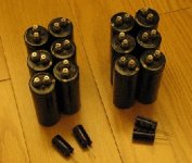
Can you imagine two mono blocks . . . ?
The big cap says 35WV 33000uF CE-SM 85degC (M) . . .
Total 6 per mono block . . .
The small cap (wakeupcall cap) says 35V 2200uF 85degC (M) . . .
No, not audiophile quality . . .
I could not find inductors . . .
It seems that I should buy a small role of coil for diy . . .
Or, I just give the first trial with CRC . . .
I ordered two 110-0 110-0/ 22-0 22-0 50/60Hz 300VA transformers . . .
Attachments
[IRFP250N / IRFP9240]
I have 12 sets of IRFP250N/IRFP9240. I understand that these two have quite different gain variations. Umm . . . I would meet more 2nd harmonic distorsion, by using these sets.
[IRF140 (IR) / IRF9140 (M) - TO-3]
I got 12 second-hand sets. Hmm . . . not new, but used . . .
I am in dillemma . . . with which set I should go . . .
I could not find any others . . .
lineup said:
Zen Mod has made his ZEN-v5 using this PCB layout:
http://www.diyaudio.com/forums/showthread.php?postid=999428#post999428
006-07-03_140901_706.jpg[/IMG]
nope
that's pic of Babelfish J,not ZV5
Okay, Zen ModZen Mod said:that's pic of Babelfish J,not ZV5
But this is, I hope
a PCB layout for Zen v5:
http://www.diyaudio.com/forums/showthread.php?postid=522655#post522655
lineup said:
MEGA-amp used this PCB layout ( by PedroPO ) detailed photos provided:
http://www.diyaudio.com/forums/showthread.php?postid=522655#post522655
Myself,
I like the idea of point to point ( p2p ) direct solder construction of this amp.
Would probably be my choice for a final amplifier, too.
We use what we are comfortable with.
in usa somewhere i have heard they say:
'howdy, partner'
here in pass labs county we may say:
passdy!
babowana
passdy!
to everybody else, too
I have downloaded you wiring diagram
and will compare it to your circuit ( think I already saved the scheme )
I doubt you have done any wrong.
After all, it is not your first amp project
question, as I dont use mosfet very much
the pins at power mosfet are,
left to right: G D S
corresponding to: B C E
is that right?
>I<
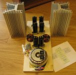
Collection of bad and ugly things is almost done . . .
For the CLC filter, I wanted to have 2mH coils, but got about 1mH . . .
XL = 2x3.14x100x0.001 = 0.628 ohms
Coil R = 0.18 ohms
So, X = 0.65 ohms
. . . the size ok? Maybe yes, maybe no . . .
Collection of bad and ugly things is almost done . . .
For the CLC filter, I wanted to have 2mH coils, but got about 1mH . . .
XL = 2x3.14x100x0.001 = 0.628 ohms
Coil R = 0.18 ohms
So, X = 0.65 ohms
. . . the size ok? Maybe yes, maybe no . . .Attachments
Babowana said:>I<
Collection of bad and ugly things is almost done . . .
For the CLC filter, I wanted to have 2mH coils, but got about 1mH . . .
XL = 2x3.14x100x0.001 = 0.628 ohms
Coil R = 0.18 ohms
So, X = 0.65 ohms
ugly!

regarding coils-you know Papa's rule of thumb-"if you can touch it for 5 secs,then it's OK"
Babowana said:>I<
Collection of bad and ugly things is almost done . . .
For the CLC filter, I wanted to have 2mH coils, but got about 1mH . . .
XL = 2x3.14x100x0.001 = 0.628 ohms
Coil R = 0.18 ohms
So, X = 0.65 ohms
JH,
At 2A of bias, your coils will drop about 2.6V with about 5.2W of power dissipated. Your coils are made from what gauge # of wire? Looking at the pics I think it'll be okay.
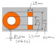
Blues said:what gauge # of wire?
1.6 mm diameter (AWG abt.14).
Inductor dimensions refer to the attached sketch.
Thanks.
Attachments
Zen Mod said:ugly!
I agree.
This is a secret project out of wife's sight . . .
Sure, she will hate both me and the ugly . . .
Umm . . . I am still useful . . .
She would throw away the ugly . . . not me . . .
Blues said:
JH,
At 2A of bias, your coils will drop about 2.6V with about 5.2W of power dissipated. Your coils are made from what gauge # of wire? Looking at the pics I think it'll be okay.
Mix up! That's 1.3V of voltage drop and 2.6W of power.
Zen Mod said:regarding coils-you know Papa's rule of thumb-"if you can touch it for 5 secs,then it's OK"
Choky, I'm a bit confused.
Is the coil getting so
 . . . ?
Coil R is 0.18 ohms, where the "dc" voltage will drop.
If DC current is 2A, the drop would be 2x0.18 = 0. 36V.
Then, power dissipation is 2 x 0.36 = 0.72W.
Meanwhile, coil impedance is 0.628 ohms, where the "ac" ripple (2 x 50Hz) would be "hopefully well" filtered. When the coil filters the ac ripple, there would be no power waste ideally. Even if there is waste of power practically, the amount would be very little. Umm . . . I might be missing something . . .
I just wondered whether the coil impedance of 0.628 ohms could filter the ripple "hopefully well", receiving help from the C behind . . .
Blues, Choky and me . . . all seem to be somewhat confused . . . as usual . . .
Babowana said:
Choky, I'm a bit confused.
Is the coil getting so
Coil R is 0.18 ohms, where the "dc" voltage will drop.
If DC current is 2A, the drop would be 2x0.18 = 0. 36V.
Then, power dissipation is 2 x 0.36 = 0.72W.
Meanwhile, coil impedance is 0.628 ohms, where the "ac" ripple (2 x 50Hz) would be "hopefully well" filtered. When the coil filters the ac ripple, there would be no power waste ideally. Even if there is waste of power practically, the amount would be very little. Umm . . . I might be missing something . . .
I just wondered whether the coil impedance of 0.628 ohms could filter the ripple "hopefully well", receiving help from the C behind . . .
Blues, Choky and me . . . all seem to be somewhat confused . . . as usual . . .
in your case you need to make calculations just for DC losses
P=I^2 x Rdc = 4 x 0,18=0,72W
what I wrote is a joke...........read between the lines
that was just a remainder how Papa is practical
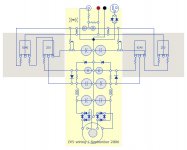
>II<
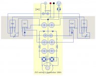
The wiring diagram shown on post#29 has an error, having
the FET-protecting diodes of opposite direction.
Corrected them and in addition re-arranged some parts . . .
The fabrication is on-going slow but well . . .
I could finish it on Sunday . . .
Ahh . . .
I want to finish . . .
before I go home for 3weekfullservice for wife . . .
Attachments
- Status
- This old topic is closed. If you want to reopen this topic, contact a moderator using the "Report Post" button.
- Home
- Amplifiers
- Pass Labs
- Papa! I want to have Zen V5.