I found a schematics in a "drawer" (some old folder in my disk). It is completely random as for part numbers and component values. I should have the optimized version somewhere, but not in that dusty folder.
It is a toy project I simulated years ago and never built.
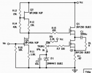
It is an amplifier that may be categorized at the border of the "zen" type. It is single ended yet push-pull, it has no (global) feedback yet it is based on strong local feedback. It has only 1 capacitor (I added a second capacitor in a polarization network but don't know if it is needed; certainly in the simulation it has no effect).
The first stage has gain and an active load on the drain. It is a load, but it is active and if optimized (if this is at all possible in practice) it is quite linear. Not too much, however.
The whole first stage is nice to look at and provides matter for philosophical bla-bla(*), but probably any op-amp based stage would do much better.
The second stage is a follower with an active load on the source. It is a load, but it is active and it works in push-pull.
The end of the story is that you can double the current on the load RL for a given output swing, and this means that it needs half the quiescent current (1/4 the quiescent power dissipation) w.r.t. a standard class-A stage. And, being push-pull and with local feedback (source degeneration), it is also much more linear.
I would be very curious to know whether it works, so if anyone has some spare power MOSFETS and time to kill...
--st.r.
(*) The first and second stage are antisymmetric: the load is above the active device in the first, the load is under in the second. Both are fet, but J- on the left and MOS- on the right. So the topology is a sort of ying-yang symbol. The left has voltage gain, the right has current gain. It also has left-to right and top-to-bottom symmetry, just like the four elements in the Western tradition. If the load is female (receiving) and the active element is male (giving), they complement each other because both are needed for linearity. Power supply is single, so that earth and air are clearly defined. Also fire (voltage) on the left and water (current) on the right. The circuit is set as to work as a whole, where all parts have a role. This is how capacitors have all been banned except one (which is critical). And so on...
Should I continue, or Zen circuitists have already been converted? I should try and sell it to Dan Brown.
It is a toy project I simulated years ago and never built.
It is an amplifier that may be categorized at the border of the "zen" type. It is single ended yet push-pull, it has no (global) feedback yet it is based on strong local feedback. It has only 1 capacitor (I added a second capacitor in a polarization network but don't know if it is needed; certainly in the simulation it has no effect).
The first stage has gain and an active load on the drain. It is a load, but it is active and if optimized (if this is at all possible in practice) it is quite linear. Not too much, however.
The whole first stage is nice to look at and provides matter for philosophical bla-bla(*), but probably any op-amp based stage would do much better.
The second stage is a follower with an active load on the source. It is a load, but it is active and it works in push-pull.
The end of the story is that you can double the current on the load RL for a given output swing, and this means that it needs half the quiescent current (1/4 the quiescent power dissipation) w.r.t. a standard class-A stage. And, being push-pull and with local feedback (source degeneration), it is also much more linear.
I would be very curious to know whether it works, so if anyone has some spare power MOSFETS and time to kill...
--st.r.
(*) The first and second stage are antisymmetric: the load is above the active device in the first, the load is under in the second. Both are fet, but J- on the left and MOS- on the right. So the topology is a sort of ying-yang symbol. The left has voltage gain, the right has current gain. It also has left-to right and top-to-bottom symmetry, just like the four elements in the Western tradition. If the load is female (receiving) and the active element is male (giving), they complement each other because both are needed for linearity. Power supply is single, so that earth and air are clearly defined. Also fire (voltage) on the left and water (current) on the right. The circuit is set as to work as a whole, where all parts have a role. This is how capacitors have all been banned except one (which is critical). And so on...
Should I continue, or Zen circuitists have already been converted? I should try and sell it to Dan Brown.
Attachments
I think that's quite clever, although I believe you will have to
individually adjust R1 against the apparent resistance of the
current source Mosfet to get the current sharing figure you
want. It would be interesting to compare this to a circuit
where R1 is replaced by a constant current source.

individually adjust R1 against the apparent resistance of the
current source Mosfet to get the current sharing figure you
want. It would be interesting to compare this to a circuit
where R1 is replaced by a constant current source.
IThank you for your comments.
> individually adjust R1 against the apparent resistance of the
> current source Mosfet to get the current sharing figure you want.
I did simulations for several values of R1 and of course there is an optimum, but in the worst case (R1=0) the "low" MOS (Q2) becomes a constant current source and all reduces to a standard source follower.
> It would be interesting to compare this to a circuit
> where R1 is replaced by a constant current source.
You need R1 to sense the current on the load and modulate the source of Q2, so to have a variable VGS2 and obtain the push-pull operation.
Note that I cheated. It is not really class A. If Q2 shuts down, there is some distortion but not clipping.
On the other hand, I stress once more that I have only simulated the whole thing.
Regards,
--st.r.
st r said:You need R1 to sense the current on the load and modulate the source of Q2, so to have a variable VGS2 and obtain the push-pull operation.
mmmmm... actually you need a non-zero impedance, and a
current source would nail the current value down so that the
sum of the load through the follower plus the load would be
a constant.
You could stress that againOn the other hand, I stress once more that I have only simulated the whole thing.
Steen
> You could stress that again
Some time ago I played with this circuit and proposed it to a similar, Italian forum. However as far as I know no one has dared to try it.
It's been 15, maybe 20 years since I last touched a solderiong iron (except for making minor repairs at home).
--st.r.
Some time ago I played with this circuit and proposed it to a similar, Italian forum. However as far as I know no one has dared to try it.
It's been 15, maybe 20 years since I last touched a solderiong iron (except for making minor repairs at home).
--st.r.
This amplifier is implemented and imett positive comments about the sound
http://www.vegalab.ru/forum/showthread.php/40283-%D0%A3%D0%9C%D0%97%D0%A7-PowerAmp-01
Îòçûâû î çâó÷àíèè óñèëèòåëÿ Poweramp-01
Petr
http://www.vegalab.ru/forum/showthread.php/40283-%D0%A3%D0%9C%D0%97%D0%A7-PowerAmp-01
Îòçûâû î çâó÷àíèè óñèëèòåëÿ Poweramp-01
Petr
Parameters of the output stage can be significantly improved if we use these ideas here
Taylor Source Follower
Petr
Taylor Source Follower
Petr
Interesting. I practiced the feedback loop starting C1 through the 8 Ohm loudspeaker and the source resistor [0.47 Ohm]. It gave a different sound character versus grounding the loudspeaker.I found a schematics in a "drawer" (some old folder in my disk). It is completely random as for part numbers and component values. I should have the optimized version somewhere, but not in that dusty folder.
It is a toy project I simulated years ago and never built.
It is an amplifier that may be categorized at the border of the "zen" type. It is single ended yet push-pull, it has no (global) feedback yet it is based on strong local feedback. It has only 1 capacitor (I added a second capacitor in a polarization network but don't know if it is needed; certainly in the simulation it has no effect).
The first stage has gain and an active load on the drain. It is a load, but it is active and if optimized (if this is at all possible in practice) it is quite linear. Not too much, however.
The whole first stage is nice to look at and provides matter for philosophical bla-bla(*), but probably any op-amp based stage would do much better.
The second stage is a follower with an active load on the source. It is a load, but it is active and it works in push-pull.
The end of the story is that you can double the current on the load RL for a given output swing, and this means that it needs half the quiescent current (1/4 the quiescent power dissipation) w.r.t. a standard class-A stage. And, being push-pull and with local feedback (source degeneration), it is also much more linear.
I would be very curious to know whether it works, so if anyone has some spare power MOSFETS and time to kill...
--st.r.
(*) The first and second stage are antisymmetric: the load is above the active device in the first, the load is under in the second. Both are fet, but J- on the left and MOS- on the right. So the topology is a sort of ying-yang symbol. The left has voltage gain, the right has current gain. It also has left-to right and top-to-bottom symmetry, just like the four elements in the Western tradition. If the load is female (receiving) and the active element is male (giving), they complement each other because both are needed for linearity. Power supply is single, so that earth and air are clearly defined. Also fire (voltage) on the left and water (current) on the right. The circuit is set as to work as a whole, where all parts have a role. This is how capacitors have all been banned except one (which is critical). And so on...
Should I continue, or Zen circuitists have already been converted? I should try and sell it to Dan Brown.
- Status
- This old topic is closed. If you want to reopen this topic, contact a moderator using the "Report Post" button.
- Home
- Amplifiers
- Pass Labs
- ino, a possible single-ended push pull amplifier