I had two audiophile friends over this weekend, and after a nice dinner and a couple of brews we decided to take a dive into the junkbox and build something just for fun. To keep things as simple as possible we went for an resistor loaded single gain stage Mosfet amp. One mosfet, two resistors, two caps and a voltage divider for the bias, it won´t get much simpler than that.
The first attempt failed miserably due to the fact that I don´t have a line stage, my passive volume control interacted with the Mosfet´s input capacitance and cut off everything above a few kHz.
Some kind of input buffer would be the solution, and after some discussions and a few more beers we decided to copy the ZV4 buffer, using IRF9610´s since that was what I had at home.
By using this buffer and a trimpot for some level shifting we also got rid of the input capacitor, very clever if I may say so myself.
After fiddling with this primitive amp all night we listened to a couple of records early in the morning, and the sound quality was quite amazing. This amp matched my FE167E-based speakers perfectly!
Inspired by this great success I decided to build a bigger and better version. I began working on it yesterday afternoon, and now I´m almost finished.
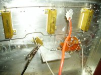
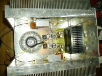
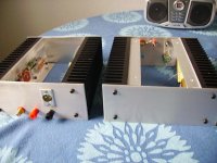
As you can see the channels are hardwired to the heatsinks (which I got from a dump).
The capacitance multiplier PSU is salvaged from an old project.
Idling at about 80W per channel, this amp should be good for almost 3W out!!!

The first attempt failed miserably due to the fact that I don´t have a line stage, my passive volume control interacted with the Mosfet´s input capacitance and cut off everything above a few kHz.
Some kind of input buffer would be the solution, and after some discussions and a few more beers we decided to copy the ZV4 buffer, using IRF9610´s since that was what I had at home.
By using this buffer and a trimpot for some level shifting we also got rid of the input capacitor, very clever if I may say so myself.
After fiddling with this primitive amp all night we listened to a couple of records early in the morning, and the sound quality was quite amazing. This amp matched my FE167E-based speakers perfectly!
Inspired by this great success I decided to build a bigger and better version. I began working on it yesterday afternoon, and now I´m almost finished.
As you can see the channels are hardwired to the heatsinks (which I got from a dump).
The capacitance multiplier PSU is salvaged from an old project.
Idling at about 80W per channel, this amp should be good for almost 3W out!!!
Attachments
Fuling said:Jeeez, I got censored!!
!
hehe
wellcome to the club

btw-where's that dump?

Hehe, don´t bother looking for that dump, we took all seven of those heatsinks that we found.
A friend took four and I got three, each one is capable of dissipating at least 100W of heat. Probably even more, but I like to run my stuff reasonably cool.
The hottest part in this amp is the heatsink for the cap multiplier...
Wow, I got censored again.
Let´s rename this thing to "Brother-in-law of Zen" instead of Bastard son of Zen

I've changed your title
Good, thanks!
"Boy friend of Zen
Um, gotta think about that for a while
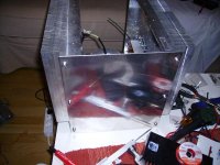
The amp is now almost finished, all that is left to to is to drill some holes in the top cover.
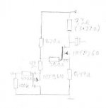
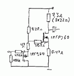
I noticed that the bias changes quite a bit during warmup, so I replaced the 47 ohm resistor (see schematic below) with a diode and a 18 ohm resistor. Th bias is adjustable thanks to 10k trimmers in parallell with the 820 ohm resistors.
Edit: You probably have to wear your best glasses to be able to read the schematic...
Attachments
80 watt, for this amplifier to output 3 watt something !!!
What is the DC voltage supply?
80 volt x 1.0 A
50 volt x 1.6 A
or
40 volt x 2.0 A
The voltage gain is something like 14, what I can understand ( 7.3 / 0.47 ).
What is the load that this output is driving?
What is the input impedance of device at the output of this amp?
And what cap you use at output?
lot of questions
about this absurd creation
from
lineup

Lineup:
A resistor loaded gain stage is the most inefficent way to build a power amp, max theoretical efficiency is 4% (correct me if I´m wrong here).
The MkII operated at something like 28V and 2,85A per channel, with 7,3 (3X22) ohms drain resistors I got about 3W out.
The MkIII runs at 24V and the drain resistors has been increased to 11 ohms to raise the output impedance a bit. Quiesent current is 1,6-1,7A per channel, this should be good for just more than 1W per channel...
I finished (well, almost finished) the monos about an hour ago and they are playing sweet music right now.
It seems that the heatsinks can take a bit more heat so I´ll aim for 28-30V when I build the final power supplies. Currently I use some old regulated 24V surplus PSU:s.
The output caps are really cheap ones that I had at home, they will be changed to to something better later on.
Thanks
fellow countryman.
those informations will be enough for several others to try this, at home
few parts, but with very high quality, is the best way
when trying to build simple amplifiers running in hot class a
it is not like more normally complicated advanced many parts class ab
where very high values of negative feedback
is used
to correct for not so good quality parts
and not very optimal design and other flaws
for those that have no time to build things properly
or just dont know how
if I had to chose between some extreme class ab constructions
at this forum
( there are plenty of them, including all chip amps running in lots of negative feedback )
and the other way,
like this your Brother-in-Law-to-Zen
or some other simple but good Class A amps like SEWA
you do not have to think for long
to know
what would be my choice
Regards
lineup A dedicated Class A amplifier guy
fellow countryman.
those informations will be enough for several others to try this, at home
few parts, but with very high quality, is the best way
when trying to build simple amplifiers running in hot class a
it is not like more normally complicated advanced many parts class ab
where very high values of negative feedback
is used
to correct for not so good quality parts
and not very optimal design and other flaws
for those that have no time to build things properly
or just dont know how
if I had to chose between some extreme class ab constructions
at this forum
( there are plenty of them, including all chip amps running in lots of negative feedback )
and the other way,
like this your Brother-in-Law-to-Zen
or some other simple but good Class A amps like SEWA
you do not have to think for long
to know
what would be my choice
Regards
lineup
A dedicated Class A amplifier guy- Status
- This old topic is closed. If you want to reopen this topic, contact a moderator using the "Report Post" button.
- Home
- Amplifiers
- Pass Labs
- Brother-in-law of Zen