Some additional info:
The load seen by the mosfet is about 5 ohms (11ohms in // with 8ohm speaker) and the source resistor is 0,68ohms in this version so the gain should be about 7,35.
In this version I use 75645P mosfets instead of IRFP260 simply for sonic reasons, it seems that the the latter has higher input capacitans which ruins the highs.
I don´t know anything about those 75645P:s but I had them at home and they definitely sound better than IRFP260.
Using bigger msofets than necessary is a bad idea due to the Ciss-related problems.
I will use these amps to drive my FE167E BR speakers, next in the pipeline is a SEWA for the subwoofers
I hope Nelson and/or the other Guys here in Pass forum
will add some comments on those MOSFET.
I do not know so much as they do.
Regarding if you want to / have to use more robust MOSFET
with a bit higher input capacitance, Ciss,
this is possible to do.
But when we are beginning to talk 1500 - 2500 pF,
I would think it is important not to have too little current in input IRF9610 stage.
Low Ciss MOSFET for example lateral mosfets:
2SK1058, 600 pF
2SK1530, 900 pF
.. can sometimes be driven with as little current as 10 mA at input.
Now you already has got ~25 mA in IRF9610 ( 20V / 820 Ohm )
and so you would have some margin and do not have to worry.
And if you want to increase later, IRF9610, which is TO-220 can take more Watts.
But you should not increase current, if you dont have to,
because if a transistor get hotter, the less good it will work.
At least in some parameters.
No transistor should be set to work more than necessary.
This is about Watt, Power, temperature and heatsinks.
The trick is to find a good balance.
This is where guys like Nelson Pass and others with MOSFET Experience are good to have.
They would have the experience needed to give an advice
that will come closer to reality.
I find amplifier construction, is very much about set currents in each stage:
not too little and not too much.
And find some transistor device that can do this work in the best possible way.
lineup
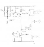
Fuling said:The schematic, exactly as built.
I like it
") simple
simple BTW, I wonder why you give okay to the high output impedance . . .
Why not lowering output impedance by scaling down 33R, 68R, 0R68 and 2x11R . . . ?
I eagerly like to know your conclusion. All the best!
The high output impedance is actually not a bad thing in my case. Some speakers requires high electrical damping from the amplifier, my speakers OTOH sounds much better with low DF amps.
Using resistors was a part of the plan to achieve this, otherwise I would never have built anything this inefficient
Using resistors was a part of the plan to achieve this, otherwise I would never have built anything this inefficient
Fuling said:And the guts:
whoa!
how thick are those backplates of the heatsinks?how thick are those backplates of the heatsinks
5mm or so, but there´s a frame that makes it look more like 30mm
""my speakers OTOH sounds much better with low DF amps.
Using resistors was a part of the plan to achieve this, otherwise I would never have built anything this inefficient""
some of my class-a amps have also low df and the bass is
as good as that of a bassy amp with hi df only there is less coloration in the speakers with low df, it is amazing what
you find when you actually experiment a little
john
Some speakers benefits from low DF, other certainly doesn´t.
My FE167E BR speakers sound really thin and lacks treble when they are driven by ordinary, high DF amps.
I´ve experimented with different drain resistors in this amp, 7,3 ohms and 11 ohms, and the lower value gives better bass but slighly muted highs while the higher value improves the HF but makes the bass slightly "floppy".
Since I´m crossing over to a pair of active stereo subwoofers at 90Hz I prefer 11ohms to get the treble right.
Edit: I´m planning to bring the monoblocks over to a friend who has Fidelio horns with Lowther drivers.
That will be VERY interesting!
Fuling said:my speakers OTOH sounds much better with low DF amps.
I see.
I do not know what your rail voltage is.
If it is +20V or higher, how about the current source R (zener bias) somewhat greater than 1.5K, e.g. about 4.75K . . . ?
Fuling said:Lineup:
A resistor loaded gain stage is the most inefficient way to build a power amp, max theoretical efficiency is 4% (correct me if I´m wrong here).
The MkII operated at something like 28V and 2,85A per channel, with 7,3 (3X22) ohms drain resistors I got about 3W out.
The MkIII runs at 24V and the drain resistors has been increased to 11 ohms to raise the output impedance a bit. Quiesent current is 1,6-1,7A per channel, this should be good for just more than 1W per channel...
I finished (well, almost finished) the monos about an hour ago and they are playing sweet music right now.
It seems that the heatsinks can take a bit more heat so I´ll aim for 28-30V when I build the final power supplies. Currently I use some old regulated 24V surplus PSU:s.
The output caps are really cheap ones that I had at home, they will be changed to to something better later on.
Babowana said:
I see.
I do not know what your rail voltage is.
If it is +20V or higher, how about the current source R (zener bias) somewhat greater than 1.5K, e.g. about 4.75K . . . ?
I know people posting here can read. It is just that they dont.
Instead they may ask same questions as was answered before.
Sometimes several times before in a topic.
When we post a new topic, we have to search first.
Same is good when we post.
At least we might read the topic and see, so we need not ask questions already answered.
I know this myself, from my topics.
Some comments and question just shows that person or critical members dont even know correctly what topic is about.
they havent ev3n read the introduction in my first.
Such questions I just leave.
As they do not even know what I am talking about:
- What time is it?
- North West part of Indonesia, thank you!
======================================
Fuling:
It seems that the heatsinks can take a bit more heat so I´ll aim for 28-30V when I build the final power supplies.
Currently I use some old regulated 24V surplus PSU:s.
Regards
to everybody
lineup
lineup said:Some comments and question just shows that person or critical members dont even know correctly what topic is about.

I do not know myself whether I am a person or a critical member.
The judgement on me is yours . . .
The judgement on you is of course mine
I was referring to the final schematic in the post #24,
where the rail voltage was not indicated.
I could assume the voltage as 24V, but was not 100% sure.
Hmm . . . I did not give any question about the rail voltage . . .
I was actually intersted in the size of the zener-biasing current
source resistor, with respect to noise . . . I thought that 4.75K
might be better than 1.5K when the rail voltage was 20V or greater . . .

Speaking about these horrible amps, how about this one?
In my opinion that driver stage much more horrible than the efficiency, to be honest. Mosfets has input capacitances that requires quite grunty driver stages, 12AX7 is very far from that.
Aim for something that draws at least 30mA or so, preferably even higher.
Just my two cents.
I´ve been messing around a bit with tubes and mosfet followers together and it ain´t easy to get it right unfortunately.
The supply voltage for the newest version is 24V, but I will increase that slightly when I get around to build some decent power supplies. The bias network in the CCS will also be upgraded, I ordered some multiturn trimpots and better decoupling caps yesterday.
Fuling said:
In my opinion that driver stage much more horrible than the efficiency, to be honest. Mosfets has input capacitances that requires quite grunty driver stages, 12AX7 is very far from that.
Sure. But there are people who are convinced that it should be done this way
On the other hand - it is not any worse than the SE MOSFET working into resistive, inductive or bulb load. The opposite is true
.Version 3.2 is in progress, I´m using the same chassis as MkIII but the circuitry will go through some minor changes:
1: The 22R and 0,68R power resistors will be replaced with 20 and 0,5R Caddock thick film resistors in T0-220 package.
The reason behind this is that the Caddocks has 1% tolerance, much better than 5-10% for ordinary power resistors.
These resistors sets the gain, so low tolerance is mandatory.
2: Better CCS with 3xLED as voltage reference and multiturn trimmers for the bias. This time I will remove the CCS mosfet from the heatsink to get better thermal stability.
3: Better output caps, 2x3300uF low impedance electrolytics shunted with 6,8uF polyprops.
4: Better power supplies, the ones I have are completely worthless.
5: I´m aiming to do a much better job wiring up the circuits this time, the MkIII looks lite a mess inside.
An updated schematic will be uploaded within a couple of days.
Version 3.2 is in progress, I´m using the same chassis as MkIII but the circuitry will go through some minor changes:
1: The 22R and 0,68R power resistors will be replaced with 20 and 0,5R Caddock thick film resistors in T0-220 package.
The reason behind this is that the Caddocks has 1% tolerance, much better than 5-10% for ordinary power resistors.
These resistors sets the gain, so low tolerance is mandatory.
2: Better CCS with 3xLED as voltage reference and multiturn trimmers for the bias. This time I will remove the CCS mosfet from the heatsink to get better thermal stability.
3: Better output caps, 2x3300uF low impedance electrolytics shunted with 6,8uF polyprops.
4: Better power supplies, the ones I have are completely worthless.
5: I´m aiming to do a much better job wiring up the circuits this time, the MkIII looks lite a mess inside.
An updated schematic will be uploaded within a couple of days.
That is good, Fuling.
I forgot to mention, regarding my talk of Input Capacitance, Ciss.
You said you think you got some loss in high frequency. But you have not actually measured the frequency slope at hi-freq, at amplifier output??
Now input capacitance of HEXFET is not everything. This is what Nelson Pass will tell you, if you ask him.
But most would agree, low input capacitance, pF, is a good thing for INPUT STAGE.
In this case the IRF9610 GATE.
Some figures of other used input transistors.
Not exact figures. But shows somewhat. For BJT small signals, more often Cob, output capacitance is specified.
[*]BC550, BC560 ~9-10 pF
[*]Lownoise Toshiba 2SA970, 2SC2240, 2SA1015, 2SC1815, maybe like 5 pF
[*]2SK117, lownoise JFET: 13 pF
[*]2SK170, lownoise JFET: 30 pF
[*]IRF610,, TO220 N HEXFET: 140 pF
[*]IRF9610, TO220 P HEXFET: 170 pF
[/list=a]
Now any transistor can be driven good, and when you have enough input current drive
this will make distortion coming from Ciss less noticiable.
The RULE: Cure for capacitance is CURRENT = more elektrons, Columb, charge
Like when we charge an electrolytic capacitor.
Current flow = voltage / resistance.
In input, we have an input signal about +-1 volt,
working into input Impedance.
I am in favor of using lower input impedance.
This will make more current flow in my cables and more current to drive input transistor will be there.
My Bottomline :
I suggest you try to lower input resistance to lineup level
At least make a try to feed IRF9610, 170p pF,
with something like 10 - 22 kohm
Instead of like 100 kohm in BOZ input and 150 kohm in your last version of this amplifier.
I refer to this schematic in post:
http://www.diyaudio.com/forums/showthread.php?postid=1026468#post1026468
About your other changes / improvements:
They all make some sense, and all together,
I am sure new version will be more HI FI.
After all, first version was only a quick experiment, as I get it.
Regards
lineup
Yes but is there a RULE how much current is nedded?The RULE: Cure for capacitance is CURRENT = more elektrons, Columb, charge
I´ve done no measurements at all on this amplifier, but without input buffer the lack of HF was obvious.
I forgot to mention that the new version will operate at twice the current in the input stage, 30mA instead of 15mA. This should (theoretically) reduce distortion in the output stage.
I use 150k input resistors simply because that´s what I use in my four channel tube amp, and since I´m going to use the same active crossover I want the impedance to match.
- Status
- This old topic is closed. If you want to reopen this topic, contact a moderator using the "Report Post" button.
- Home
- Amplifiers
- Pass Labs
- Brother-in-law of Zen