So.. I just tested my aleph P 1.7 with boards from veteran.
Sound is full, rich, bass is better, overall it is just smooth and i could,nt be happier!
Thanx Mr. Pass and thanx Damian (Veteran) who made the PCB,s.
The only "fancy" parts i have used is BG N Caps.
Volume control is an ALPS Blue Velvet 10k on the output.
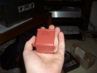
Everything is mounted in a shoebox (for now)
So only one question.. the Fet,s are getting very warm.. do they need a heatsink?
I have a small heatsink on the PSU but not on the amp boards..
Best regards and thanx for this extraordinary forum!
Joakim
Sound is full, rich, bass is better, overall it is just smooth and i could,nt be happier!
Thanx Mr. Pass and thanx Damian (Veteran) who made the PCB,s.
The only "fancy" parts i have used is BG N Caps.
Volume control is an ALPS Blue Velvet 10k on the output.
Everything is mounted in a shoebox
(for now)So only one question.. the Fet,s are getting very warm.. do they need a heatsink?
I have a small heatsink on the PSU but not on the amp boards..
Best regards and thanx for this extraordinary forum!
Joakim
I did some searching
Ok so a small heatsink i wise i guess..
However, i thought that i could place a 10k pot on the output ( wich a have) But searching a bit i came across something Nelson Pass wrote..
Ok so a small heatsink i wise i guess..
However, i thought that i could place a 10k pot on the output ( wich a have) But searching a bit i came across something Nelson Pass wrote..
There a three places you can put variable resistance in an
Aleph P to alter the gain
1) You can place a dual potentiometer on the inputs as a
voltage divider. (dual pot required for 1 channel balanced)
A good value for this is 10K to 25K
2) You can place a single potentiometer between the Source
pins of the Mosfets, where a good value is about 1 Kohm.
3) You can place a dual potentiometer as a resistive load at
the outputs (again 1 dual for each channel) to load the
current-source output, and here a good value is about 1 Kohm.
It seams i hade it all wrong.. even though it realy sounds good now,, What do i gain if connecting the pot on the input instead.?
/Joakim
2) You can place a single potentiometer between the Source
pins of the Mosfets, where a good value is about 1 Kohm.
And thus one dual pot for both channels? Between the sourcepin och which mosfet exactly?
I suggest you to put your 10k pot on the input.
10k pot on output would make the output impendence of the P1.7 preamp to be almost 10k , which is a little bit high.
If you move your 10k pot to input, the output impendence will change to about 100. This low output impendence was low enough to drive all amp.
10k pot on output would make the output impendence of the P1.7 preamp to be almost 10k , which is a little bit high.
If you move your 10k pot to input, the output impendence will change to about 100. This low output impendence was low enough to drive all amp.
1)Can't say to much about this. It probably is the standard configuration for volume controls but I havent tried it. It will mess with your source impedance so that must be considered. It may also mess with the input impedance and capacitance causing a rolloff so that needs consideration also...
2) Between the source pins of the gain transistors, is what I have been doing. A 1K maybe 2-5K is about all that's usefull in my circuit. It is not exactly N.P.s 1.7 per'se. It also does not go to minimum audio out, it only changes gain in a reasonable range. You need a mute button also if you want silence from it... It has been commented by several people that this method introduces more distortion. I find this to be true also. I don't want to quote numbers but, the distortion differnces are from, unmeasureable to barely measureable at resonable input/output levels. It depends on the needed gain and on the abssolute output level you need. 1-3 Volts is pretty damn good. If you don't want to spend the money this is the easiest cheapest solution...
3)The dual pot on the output is the original configuration, other than the type of "pot" used . It has a small advantage in that it reduces everything level-wise, including the noise of your 1.7 circuit. The input Z of your next stage is important but your gain setting and average listening level should be considered also, as with option 1) and may be taylored for the most often listened to level, with lowest gain and distortion... Hope that helped...
pics
Not much but here goes...
another
Not much but here goes...
An externally hosted image should be here but it was not working when we last tested it.
another
An externally hosted image should be here but it was not working when we last tested it.
hahaha
Well, i,ll post a picture of the ultra super duper hitech casework.
Only worthy a Aleph
The chipamp rect board is only to show KMJ the size of the boards.....
/Z
Well, i,ll post a picture of the ultra super duper hitech casework.
Only worthy a Aleph
An externally hosted image should be here but it was not working when we last tested it.
The chipamp rect board is only to show KMJ the size of the boards.....
/Z

Hi wchick
I do have a partslist that i found on some other site, It is on my other computer so i,ll mail it to you later.
The FET gets hot, i will install heatsinks on them asap..
Just a small alu plate will proberly do. As you can see from my pictures, it is not completed yet..
Regarding the Caps, i,m not shure how much better the N caps are to other caps since i can,t compare it to another P 1.7 KMJ!
However i like how it sounds.. but when i find them time i,ll replace them with some russion paper in oil Caps and see if i can spot any differences...
later
/Z
Stop pestering me and return to your backyard instead!Regarding the Caps, i,m not shure how much better the N caps are to other caps since i can,t compare it to another P 1.7 KMJ!
Ill put it together first thing in ending of sept, beginning of oct. But you know that mine will be way cooler anyway
My caps (30uF for output, 10uf for the input is about half at size):
30uf
10uF
Attachments
I have my FETs mounted on a large heatsink all together.
But I made my own boards so the FETs are lined up.
I recommend to use a heatsink, those FETs get hot even with
the heatsink. I think my heatsink is on the order of 50C.
Yes the 1.7 is a sweet amp. You're going to enjoy it.
W.
But I made my own boards so the FETs are lined up.
I recommend to use a heatsink, those FETs get hot even with
the heatsink. I think my heatsink is on the order of 50C.
Yes the 1.7 is a sweet amp. You're going to enjoy it.
W.
some basic questions
Hello Zei
I see you are using only one psu board in your P1.7. Is that enough?
In the 2nd run of p 1.7 veteran´s pcb group buy many people (me included) is asking for 2 psu boards.
How is the 2k trimpot set?
Did you try new 10 and 30u caps?
In advance thanks for comments and assistance
Happy new year
- Status
- This old topic is closed. If you want to reopen this topic, contact a moderator using the "Report Post" button.
- Home
- Amplifiers
- Pass Labs
- My Aleph p1.7 sounds wonderful !