Hope someone can help me figure out this one.
I just finished wiring my boz. Fired up the psu and got 59 V DC, all looks fine. Then I connected the preamp to the psu. Did some measurements and started adjusting P102 to get the desired voltages. As I’m turning the pot I measure the voltage after R105. When I had turned the pot all the way up I only got 5 volts. Strange. Then I remeasured the supply voltage and it had dropt to less then 30 volts As I turned the pot the other way the supply voltage slowly increased back to 59 Volts.
The only thing I did different from NP’s article was to use BD239C instead of the TIP29C as I could not find it.
Any help would be greatly appreciated.
I just finished wiring my boz. Fired up the psu and got 59 V DC, all looks fine. Then I connected the preamp to the psu. Did some measurements and started adjusting P102 to get the desired voltages. As I’m turning the pot I measure the voltage after R105. When I had turned the pot all the way up I only got 5 volts. Strange. Then I remeasured the supply voltage and it had dropt to less then 30 volts
As I turned the pot the other way the supply voltage slowly increased back to 59 Volts.The only thing I did different from NP’s article was to use BD239C instead of the TIP29C as I could not find it.
Any help would be greatly appreciated.
It sounds like you've got something wired wrong...
Somehow or other, the current drawn from the supply is increasing as you change the setting of that pot.
Looking at the schematic, the connection to the FET through R105 is meant to set a bias voltage on the gate of Q101. Virtually no current flows through this path from the wiper of the pot. The FET has a high input impedance, and the other resistors in series to the supply are all of a high value except for R102.
Notice that the pot, P102 is market CW, CCW, and W. That's clockwise, counterclockwise, and wiper. At the clockwise end you should have about 15V (as marked) always, since the current flows through the 33K, then the 10K to ground. So 25% of the resistance is below that point, and 75% is above. Adjusting the pot should only vary how much of that 15V is seen at the gate of Q101.
Even if the pot were replaced with a straight wire to ground, the supply should not be loaded down appreciably. The circuit is designed to send 40mA through Q101 (via R104) according to Nelson, and if the left side of R101 were connected to ground, it should only conduct 60V / 33.2K = .0018 amps (1.8mA) through that path. That's nothing compared to the 40Ma.
Check the value of the components and their wiring, particulary R101, P102, R103, R105.
I'm having trouble guessing just how it's wrong, but something isn't right. I hope this is some help.
Thanks for replying Vince.
I was also thinking that the supply was loaded down, the weird thing is that DC after rectifier diodes remains unchanged. So my only guess then would be too much current is drawn thru Q1 in the psu. But the BD239C is rated at 2A so I can’t see how that much can be drawn.
I will try to measure how much current is drawn from the psu later today.
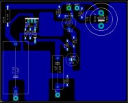
In the meantime her is the pcb layout that I made, I cant se any errors and I checked all the values. But maybe I’ve gone blind or something. Sometimes it can be hard to see ones own mistakes.
I was also thinking that the supply was loaded down, the weird thing is that DC after rectifier diodes remains unchanged. So my only guess then would be too much current is drawn thru Q1 in the psu. But the BD239C is rated at 2A so I can’t see how that much can be drawn.
I will try to measure how much current is drawn from the psu later today.
In the meantime her is the pcb layout that I made, I cant se any errors and I checked all the values. But maybe I’ve gone blind or something. Sometimes it can be hard to see ones own mistakes.
Attachments
Try measuring the voltage at the Source pin of the
MOSFET. Presuming that there is a resistor
connected from the Source to Ground, the voltage
you measure divided by the resistor value will tell you
how much current is flowing through Q1.
Just because the MOSFET is rated for 2A doesn't mean
it won't happily attempt to conduct more than that
value when its Gate voltage is high enough.... right up
to its untimely demise. Faithful little buggers,
aren't they?
eL
ELarson's right.
You've got a number of potential current paths. Just measure the voltage drops across the resistors and calculate the current flow with ohm's law. I'd start with the very first resistor downstream of the regulator transistor (R2 or R3) and find out just how much current the circuit is drawing. Then look farther downstream to find where it's going.
I'm guessing that you're only operating one channel at this time, is that right? Either way, do you get the same action with the other channel?
Thanks to both of you for replying.
This is the measurements I have done today.
Current drawn from psu, one channel driven.
P102 full ccw: 1.3mA
P102 full cw: 10mA. Jumps to 20+ when power is applied, then rapidly sinks to 10.
Current drawn by Q101:
Both channels driven:
P102 full ccw 0mA
P102 full cw 0.5mA. With only one channel driven it is 1.0mA
When both channels connected and P102/P202 at full cw, the supply voltage has dropt to an unbelievably 18V
It seems somehow that the supply can’t provide more then max 10mA. I tried changing the BD239C with a new one. Same result.
And an other thing that jumps to mind is that I hade to use 7 10V zener’s to get close to 60V. With 6 zener’s I only got about 50V. Don’t know if that means anything to you? Bad zener?
The xformer I’m using is a 2x28V 50VA toroid.
I’m seriously considering trying to connect the unregulated 78V DC to the preamp. Not permanent of course, but just to isolate the problem. If it works with unregulated power it must be the BD239C, right? Any views on doing this? Or is there a way I can measure max current from psu?
Thanks again.
Kermit - What voltages do you measure at the 3 pins
of the BD239C when the pot is turned all the way up
and then all the way down?
It's interesting that with 77-78 volts unregulated that
a stack of 7 10V zeners only gave you about 60 volts.
Are you using the 4750 ohm resistor to feed the zeners
and the base of the BD239C? Perhaps you could try a
somewhat smaller resistor (2200 ohms, say) to feed
the stack with a bit more current (and also the Base
of the transistor, of course.)
Erik
Thanks Erik.
I finally got around to do some measurements. This is what I get after removing the extra zener and paralleling R1 with a second 4750 resistor. R1 is now 2375 ohm. The voltages at the pins of BD239C is:
Base: 60V
Collector: 86V no load, 85,6V P101/102 full cw.
Emitter: 48V no load 24V both channels full cw.
On the upside I now have a total of 10mA on both channels, so it appears you are on to something with the lowering of R1. Il put a pot in there and try to adjust it until I get a stable output.
Thanks for helping out!
If you can find the nominal current rating (Iz)of the zener diodes (how much to get the zener voltage?) then you can figure it out.
R= (86-64)/Iz. That way you'll set the current through the zeners to be what you need to get them to exhibit their zener voltage.
Other choice is to keep paralleling resistors in the range of 5K until you like what you get. According to Mr. Pass you're looking for 64 volts at the base of the transistor. Then leave it or measure it and replace it with an appropriate resistor. As long as the current is enough, it's not critical what the value is. (10-20% too much current won't matter).
Good luck. Congrats on progress.
Kermit said:Thanks Erik.
I finally got around to do some measurements. This is what I get after removing the extra zener and paralleling R1 with a second 4750 resistor. R1 is now 2375 ohm. The voltages at the pins of BD239C is:
Base: 60V
Collector: 86V no load, 85,6V P101/102 full cw.
Emitter: 48V no load 24V both channels full cw.
On the upside I now have a total of 10mA on both channels, so it appears you are on to something with the lowering of R1. Il put a pot in there and try to adjust it until I get a stable output.
Thanks for helping out!
With the Base at 60V I would have expected to see about 59V
at the Emitter. Something doesn't seem right there. Do you
have a large amount of capacitance from the Emitter to ground?
(Maybe a surge current damaged your pass transistor?)
E.
And it works!!I rewired everything on a piece of perfboard last night. The pcb was a complete mess after all the soldering and desoldering. Checked all the parts, only C2 was bad I believe. The other parts were ok. After that all was fine. Probably something wrong with the pcb. After all that was my first attempt at making a pcb. Although I cant see anything wrong with it.
Ah well, it works now, so I’m happy!

Now my only concern is that the mains varies a lot here. Between 210 and 240 I believe. I have measured anything from 78 – 86V unregulated DC. Makes it hard to decide on the value of R1.
Thanks again!
- Status
- This old topic is closed. If you want to reopen this topic, contact a moderator using the "Report Post" button.
- Home
- Amplifiers
- Pass Labs
- BOZ supply voltage drops to 1/2??