square wave stuff
First - thanks AndrewT and Mad_K for looking at my wattage calculations.
Now for the square wave stuff. Mad_K was right that the bypass caps
made no difference for the square wave (or at least the square wave at
20KHz).
After looking at the Aleph 30 schematic (in the Zen Mod posting), I took a
guess at tried a 10pf, 12pf, and 15pf mica cap around R2. This also
seemed to make no difference in the 20KHz square wave. I did connect
and test a Harmon Kardon Citation 16 amplifier. I used the same
methodology as I used on the Zen 5, and the Citation produced a very
nice 20KHz square wave. So I think my method of testing is ok.
I guess I'm curious about _why_ the 20KHz square wave is not so
square. I would have expected this amp to be able to reproduce higher
frequencies than this. Are my expectations unrealistic? Should I care
about this at all? If I should care, what do I do about it?
thanks,
Robert
Attachments
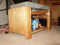
Zen Mod said:what's temp of these barbecue bars?

Well, I do not believe my meter measures aluminum correctly. However,
I believe that when idling, the steady temp is about 50-55C. When playing
music, the steady state temp is between 40 and 45C.
-- Robert
Attachments
and what's exact schematic of yours aleph?
somewhere (probably in input LTP) you have wimpy current,or....what type of output mosfets you use and how many?
for test-try disconnecting pair of output mosfets (re-set overall current) and then look have you any changes in squares....
btw-is the same case exactly with both channels?
second btw-you can try to disconnect AC modulation of CCS (220UF cap) ,to help us in determining what part is responsible for this rounding- CCS or "active" half of output.
when I think a little ,you can try this first,disconnecting pairs of mosfets second
Re: square wave stuff
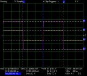
The rounding off looks somewhat too much at 20kHz. Do you have the square wave at 100kHz, too? I think that the rounding off is mainly due to internal capacitance on the signal path combined with resistance, which form a kind of integrator so that high frequecy roll off starts too early. Probably, you need to carefully look into whether there is any additional internal capacitance in the signal path . . . accidently added . . .
audiorob said:I guess I'm curious about _why_ the 20KHz square wave is not so
square. I would have expected this amp to be able to reproduce higher frequencies than this. Are my expectations unrealistic? Should I care about this at all? If I should care, what do I do about it?
The rounding off looks somewhat too much at 20kHz. Do you have the square wave at 100kHz, too? I think that the rounding off is mainly due to internal capacitance on the signal path combined with resistance, which form a kind of integrator so that high frequecy roll off starts too early. Probably, you need to carefully look into whether there is any additional internal capacitance in the signal path . . . accidently added . . .
Hi,
the input filter will round off the HF square waves.
It is normal to inject test waveforms after the input filter. However some amplifiers become unstable when the input is loaded this way.
I see your sample rate is 1Mb/S. This is far too slow to detect oscillation. You only have about 24 samples per half wave. Is this a clue to the rounding? Software taking a guess at what it thinks it should show you?
Zen Mod said:and what's exact schematic of yours aleph?
somewhere (probably in input LTP) you have wimpy current,or....what type of output mosfets you use and how many?
<snip>
btw-is the same case exactly with both channels?
<snip>
This is a Zen 5 (complementary Zen), that was built exactly as specified (to the
best of my ability) in Nelson's paper, with the following exceptions:
1) Almost all of my resistors are 1/2 watt, not 1/4 watt. R1 and R2 are 1/4 watt.
All resistors are 1%. R7 and R8 are matched. R5 and R6 are matched.
2) R9-R10 were replaced by a single 0.27 ohm 15W resistor, as well as R11-R12.
These are also matched.
3) The power supply caps C4-C9 are 40,000uF.
For completeness sake:
The transformers are 1KVA, 30V secondaries. I am regulating the power
supply rails at +/- 30V. The power supply uses aluminum bus bar, and 12
gauge wiring, except for the voltage regulation section. I used 16ga. wire to
the voltage regulation transistors drain and source, and 24ga. wire to the gates.
I used 16ga wire from the power supply to the amplifier board. I think I have
posted pictures of the power supply before putting them into boxes, but let
me know if we need more.
The amplifier circuit uses point to point wiring, and is half the size of Nelson's
schematic of the circuit (Fig. 3). I do use terminal blocks to connect the
transistors to the circuit, for power to the circuit, and for the input. I used
24ga wire for the inputs, and 16ga wire for the output. All wiring is stranded
copper, and are reasonably short lengths.
The transistors are IRFP240 and 9240's (one of each for amplification, one
of each for voltage regulation).
Yes, the square waves traces look the same between the left and right
channels (on the bright side, I'm consistant!). I do not know what an "input
LTP" is, so I don't know how to address that issue.
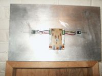
Here is a picture of the board, mounted on the heat sink, and connected
to the FETs. The wires to the FETs are about 2.5 inches long. The heat sink
is 12 inches tall by 19.5 inches wide. The board is about 3 inches by 5 inches.
thanks,
Robert
Attachments
Hi,
S P A C E D out, man!
would it help if the board was quarter of the area? 50mm by 60mm.
Should the FET gate resistors be attached to the gates?
NOT tens of cm away. The resistor body should be electrically within a few millimetres of the gate exit from the plastic package.
Is this the heatsink that lies flat instead of standing up?
How thick is the backplate?
A good guide for effective heat distribution is that ten times thickness is the effective limit for heat conduction to the extremities. Any further and the heatsink efficiency falls off.
audiorob said:
This is a Zen 5 (complementary Zen), that was built exactly as specified (to the
best of my ability) in Nelson's paper, with the following exceptions:
1) Almost all of my resistors are 1/2 watt, not 1/4 watt. R1 and R2 are 1/4 watt.
All resistors are 1%. R7 and R8 are matched. R5 and R6 are matched.
2) R9-R10 were replaced by a single 0.27 ohm 15W resistor, as well as R11-R12.
These are also matched.
3) The power supply caps C4-C9 are 40,000uF.
For completeness sake:
The transformers are 1KVA, 30V secondaries. I am regulating the power
supply rails at +/- 30V. The power supply uses aluminum bus bar, and 12
gauge wiring, except for the voltage regulation section. I used 16ga. wire to
the voltage regulation transistors drain and source, and 24ga. wire to the gates.
I used 16ga wire from the power supply to the amplifier board. I think I have
posted pictures of the power supply before putting them into boxes, but let
me know if we need more.
The amplifier circuit uses point to point wiring, and is half the size of Nelson's
schematic of the circuit (Fig. 3). I do use terminal blocks to connect the
transistors to the circuit, for power to the circuit, and for the input. I used
24ga wire for the inputs, and 16ga wire for the output. All wiring is stranded
copper, and are reasonably short lengths.
The transistors are IRFP240 and 9240's (one of each for amplification, one
of each for voltage regulation).
Yes, the square waves traces look the same between the left and right
channels (on the bright side, I'm consistant!). I do not know what an "input
LTP" is, so I don't know how to address that issue.
Here is a picture of the board, mounted on the heat sink, and connected
to the FETs. The wires to the FETs are about 2.5 inches long. The heat sink
is 12 inches tall by 19.5 inches wide. The board is about 3 inches by 5 inches.
thanks,
Robert
you know for proverb "short circuit between two earphones" ?
that's exactly what happened to me-I meant all the time on Aleph 5..........
I'll see Zen5 schmtic and rethink.....
btw- tip regarding gate stoppers is worthwhile
Re: Re: square wave stuff
I have not tried 100kHz. 20kHz is the highest that I tried.
Thanks Babowara, it was my thought too that some type of RC circuit was
causing the rounding. Here are some things that I know could cause more
resistance or capacitance than expected:
Cold or sloppy (generally bad) solder joints.
Long, or heavy guage wire.
Coils of wire.
Overheating wire.
I'm very much a novice at this, so I don't know if that list is exhaustive. Are
there other things I should try to find and avoid?
Now that I'm thinking about it, I do have a 16ga wire that runs from the drain
of 1 transistor to the drain of the other transistor (about a 3 inch length) with
a couple of solder connections to it (pretty much as it is depicted in the
Fig. 3 schematic in Nelson's article). I used 16ga wire there because I thought
that would be the section that has the most current. Might that be a possibility?
If it is, then surely the 12 inches (or so) of 16ga wire I use to connect the board
to the speaker bananna plugs would be a problem too. As would the test leads
on some of my probes. Maybe that is not the problem area. BTW, I tested a
40 foot length of Monster 11ga wire with 8 connectors will pass a 20kHz square
wave fairly accurately. Based on that, doesn't the 3 inch length of 16ga wire
sound unlikely to be the cause?
I would guess the maximum current the Zen 5 could deliver to the speakers
is about 3 amps. I'm guessing that I should use the smallest guage wire that
will carry 3 amps without getting too hot. Does that sound about right? Does
using 16 to 24ga stranded wire on this project sound reasonable?
And thinking about that, this project is so small, and the parts are so close
together that I only used about 3 wires on the board. The parts are pretty
much soldered together by their leads. And their leads were even cut to
shorter lengths. I guess there are 6 wires that go to the transistors, but I
wasn't counting those, since they connect to the board by a terminal block
(mentioned in the last post).
Has anyone else ever tried tracing a square wave through their Zen 5? If
so, what did you get?
thanks,
Robert
Babowana said:
The rounding off looks somewhat too much at 20kHz. Do you have the square wave at 100kHz, too? I think that the rounding off is mainly due to internal capacitance on the signal path combined with resistance, which form a kind of integrator so that high frequecy roll off starts too early. Probably, you need to carefully look into whether there is any additional internal capacitance in the signal path . . . accidently added . . .
I have not tried 100kHz. 20kHz is the highest that I tried.
Thanks Babowara, it was my thought too that some type of RC circuit was
causing the rounding. Here are some things that I know could cause more
resistance or capacitance than expected:
Cold or sloppy (generally bad) solder joints.
Long, or heavy guage wire.
Coils of wire.
Overheating wire.
I'm very much a novice at this, so I don't know if that list is exhaustive. Are
there other things I should try to find and avoid?
Now that I'm thinking about it, I do have a 16ga wire that runs from the drain
of 1 transistor to the drain of the other transistor (about a 3 inch length) with
a couple of solder connections to it (pretty much as it is depicted in the
Fig. 3 schematic in Nelson's article). I used 16ga wire there because I thought
that would be the section that has the most current. Might that be a possibility?
If it is, then surely the 12 inches (or so) of 16ga wire I use to connect the board
to the speaker bananna plugs would be a problem too. As would the test leads
on some of my probes. Maybe that is not the problem area. BTW, I tested a
40 foot length of Monster 11ga wire with 8 connectors will pass a 20kHz square
wave fairly accurately. Based on that, doesn't the 3 inch length of 16ga wire
sound unlikely to be the cause?
I would guess the maximum current the Zen 5 could deliver to the speakers
is about 3 amps. I'm guessing that I should use the smallest guage wire that
will carry 3 amps without getting too hot. Does that sound about right? Does
using 16 to 24ga stranded wire on this project sound reasonable?
And thinking about that, this project is so small, and the parts are so close
together that I only used about 3 wires on the board. The parts are pretty
much soldered together by their leads. And their leads were even cut to
shorter lengths. I guess there are 6 wires that go to the transistors, but I
wasn't counting those, since they connect to the board by a terminal block
(mentioned in the last post).
Has anyone else ever tried tracing a square wave through their Zen 5? If
so, what did you get?
thanks,
Robert
audiorob said:Yes, the square waves traces look the same between the left and right channels (on the bright side, I'm consistant!).
The last picture looks like Mel Gibson on the cross on the wall.

If the music is ok . . .
I would forget the sq. waves . . .
AndrewT said:Hi,
the input filter will round off the HF square waves.
It is normal to inject test waveforms after the input filter. However some amplifiers become unstable when the input is loaded this way.
I see your sample rate is 1Mb/S. This is far too slow to detect oscillation. You only have about 24 samples per half wave. Is this a clue to the rounding? Software taking a guess at what it thinks it should show you?
Thanks AndrewT.
I don't know that this circuit has any input filter (again, I'm a novice at this,
so I could be wrong).
WRT the sampling rate and precision of the scope (just to make sure we're on
the same page) the manufacturers state that the hardware is taking 1 million
samples per second, with a word size of 12 bits (12 bits per sample). Yes, I
agree that is about 20 samples per division, and about 24 samples per half
wave.
I don't know if the software interpolates data points, or exactly how the program
uses the collected data (beyond the most obvious things). But I did the same
test on a Harmon Kardon Citation 16 amp, and the scope displayed a good
square wave trace. I didn't save the trace, but I could do it again if you're
interested.
I think your point is that the scope is not sampling fast enough to show what
is really happening at the rounded corner, and you're probably right. However,
I think that the scope is showing us what it sees. I also tried some traces of
1kHz and 10kHz. Their patterns look indicative of the 20kHz trace.
Here is a 1kHz trace. The yellow trace is the input and the magenta trace is
the output. The 10kHz trace looks similar, with more rounding at the corner.
thanks,
Robert
Attachments
AndrewT said:Hi,
S P A C E D out, man!
would it help if the board was quarter of the area? 50mm by 60mm.
Should the FET gate resistors be attached to the gates?
NOT tens of cm away. The resistor body should be electrically within a few millimetres of the gate exit from the plastic package.
Is this the heatsink that lies flat instead of standing up?
How thick is the backplate?
A good guide for effective heat distribution is that ten times thickness is the effective limit for heat conduction to the extremities. Any further and the heatsink efficiency falls off.
HI AndrewT,
Thanks again for the replys - and everyone else too!
Yes, the transistors are spaced to better distribute the heat load.
The gate resistors are about 6 or 7 cm (if memory serves me, it is
about 2.4 cm/inch, right?) from the gate. The wire to the gate is 24ga
stranded cu. Is that too far? Even if it were too far, the effect would
not be to round a square wave, would it?
The backplate is 0.3 inches thick. That basicly fits your 10x rule.
And thanks for that. I did not know the 10x rule. Good info.
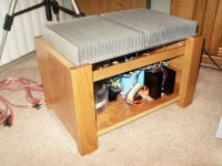
Yes, it is the heatsink that is the top piece in the pictures of the box.
Each voltage regulator has its own heatsink, which are black, and
mounted on the inside of the box.
thanks,
Robert
Hi,
the fins within a 3inch radius of each device will work very well. The fins beyond the 3inch radius will work progressively less well as the distance increases.
Unfortunately with your sink lying on it's back the effective fins are surrounded by warm air from the less effective fins and so cooling of ALL parts of the sinks are less effective than what the manufacturer intended.
Any chance you could re-jig your layout to get the fins vertical?
The FET gate resistors MUST be attached very close to the FET package on the shortest possible leg lengths.
The Datasheet gives some clue by specifying the inductance of the leads in the package.
I have seen and used resistors bent right next to their body soldered just 3mm from the package. That is short, much shorter than on a PCB.
AndrewT said:The FET gate resistors MUST be attached very close to the FET package on the shortest possible leg lengths.
In the class room, already been many discussions among students with Papa . . .
Shorter distance is better, but somewhat long is still ok . . .
Still ok with respect to the lead inductance . . .
Still ok with respect to the stray capacitance . . .
Still ok with respect to the parasitic oscillation . . .
No unexperienced policeman . . . let's be flexible . . .

- Status
- This old topic is closed. If you want to reopen this topic, contact a moderator using the "Report Post" button.
- Home
- Amplifiers
- Pass Labs
- problems building zen 5 amp