AndrewT said:Hi Bob, how much of that rise time is invented by the software or can it be relied on to be a reasonable guide?
All tools (incl. my eyes and brain) have tolerances . . .
At the rate of % error . . .
I approximate the risetime myself from his picture, assuming his tool is the one good enough and well calibrated . . .
Hi Bab,
I have seen your F-3 formula or something similar before. F-3db=350/uSrisetime
What limitations are there on it's application?
BTW. I was not referring to your eyes nor your technical ability.
I think (an opinion) his computer is telling him lies at the frequencies and sampling rates he is working at.
Another opinion, he should get a real oscilloscope preferably analogue before he comes to rely on computer generated data too often.
AndrewT said:What limitations are there on it's application?
O, I just added kidding on me myself, trying to blow off my own hard time lasting these days. . .

It is according to the book. The amplifier typically has one dominant bypass (RC) circuit that roles off the voltage gain at a rate of 20dB per decade until f(unity) is reached. The critical frequency (fc) of this bypass circuit is given by
fc=1/(2x3.14x RC)
where RC = time constant of the internal RC circuit.
In general, calculation of the internal RC value is uneasy . . . Without knowing the hidden RC value, however, we could find out the fc . . . using oscilloscope measurement.
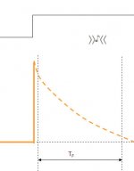
We apply a square wave at "any" certain high frequency to the amp's input and see output response through the oscilloscope. Do we see that the vertical leading edge of the square wave appears rounding-off . . . ? In this condition, we could measure the risetime (from 10% to 90% amplitude), which is always 2.2 times of the time constant, i.e. the measured Tr = 2.2RC. Then, RC=Tr/2.2 . . . We bring this into the above fc calculation formula.
fc= 2.2/(2x3.14xTr) = 0.35/Tr
I think that there is no other condition we need to consider.
We could do the same with the lower critical frequency, measuring the fallingtime (the top line of the square wave).
AndrewT said:The falling time, is that the slope on the top of the square wave?
Yes, it is also the RC curve . . .
Hi, Bab,
looking at a 100Hz square wave with a peak to peak height of 10Vpp.
The slope on the top is about 10% of the peak height i.e. 500mV
The half cycle takes 5mS.
The slope has fallen 10% in 5mS so would fall 80% in 40mS.
RC=40mS/2.2 or 40mS*2.2? which?
High pass frequency (-3db) = 1/2/Pi/RC and for 40mS, F-3=8.8Hz or 1.8Hz.
Babowana said:.
Robert,
Why you worry about your wave shape of 20kHz?
From your picture, I read the risetime (10%V to 90%V) of about 3.2 uS.
So, the upper critical frequency (-3dB) is:
fc = 0.35/3.2 * 1000 = 109kHz
The amp has bandwidth upto 100kHz.
Isn't it enuf?
Hi Babowana,
It is not that I am so worried about the 20kHz square wave, or the
bandwidth of the amp. The amps sound surprisingly good as they
are. It is more that this project is a learning tool for me (ok, and lots
of fun too), and the square wave traces do not match my expectation.
I would have expected a 20kHz square wave to look perfect through
such a simple (as in very few components) amp that uses modern,
switching type of FETs. Also, 1970 vintage amps had better square
wave performance than what my Zen does. This is not my field of
study, so maybe my expectations are unrealistic. I do not understand
why the traces are not perfectly square at 20kHz, but I would like to
understand.
Also, I do not have any distortion testing equipment, so I was using the
equipment I have to kind of "eyeball" the amp's performance. I have a
signal generator and a very slow O-scope. I looked at traces of sine,
triangle, and square waves. Square waves showed the biggest change
(do we call this distortion?) from the original at the lowest frequency of
the different wave shapes. I was surprised (not disappointed, just
surprised) that the amp did not reproduce a better square wave trace
(but what do I know).
So next I wondered if I had done something wrong when building the
amp. I still don't _know_ the answer to that, but I'm leaning towards
what I see is the normal behavior of the amp, and that I built the amp
correctly. But if I did not build the amp correctly, I want to discover
what I did wrong and correct it.
If I built the amp correctly, I would like to research how the amp could
be modified to produce a better square wave. I would like to listen
to the amp to hear if that makes a difference. Similarly, I would like to
experiment with stabilizing the current source (and voltage) maybe
by cascoding transistors. How would this sound? Would it
reduce the amount the bias and DC offset drift? I expect that this might
lead to another architecture, but I don't know. I think I would like to
play with some of these things, and gain a better understanding of what
they really do.
So is a 100kHz bw enough? Well, yes (again, I am surprised how
good this amp sounds) and no (I hope to learn more from this project).
Thank you for your bw calculation and all your comments.
Robert
audiorob said:. . . Thank you for your bw calculation and all your comments . . .
. . . The amps sound surprisingly good as they are . . .
. . . the amp did not reproduce a better square wave trace . . .
Not at all, I just enjoying in sharing our experiences . . .
Good sound? Good motivation for me . . .
If we reduce the gain of 10 to 5, by increasing R1 from 470 to 1K, the rounded leading edge would be better squared off . . . at high frequencies.
Babowana said:
Not at all, I just enjoying in sharing our experiences . . .
Good sound? Good motivation for me . . .
If we reduce the gain of 10 to 5, by increasing R1 from 470 to 1K, the rounded leading edge would be better squared off . . . at high frequencies.
I tried it, and you are quite right. BTW, I think the square
waves look better across the low freq. too (better across
the 20-20kHz range).
But does this also mean that even more voltage will be
required to drive this thing? With R1 at 470 ohms, my amps
require almost 4V to get full output. Would the impedance
matching input buffer of Zen 4 work for us too?
Robert
audiorob said:Would the impedance
matching input buffer of Zen 4 work for us too?
I think so . . .
30V rails but only 18V output???
I've been trying ot build an input buffer (or a 1st stage of amplification),
but I'm confused by the voltage I'm getting from the output stage.
Nelson mentions that the gain of the Zen 5 amp is slightly less than
R2/R1. With the specified values of R1 and R2, that was a gain of
slightly less than 10. It was taking a little more than 3V (6V peak to
peak) input to drive my Zen 5 to full output. But full voltage output was
at about 17V (34V peak to peak). This is a gain of about 6. I really
don't expect to get 30V (60V peak to peak) output, but I expected to get
higher than 17V.
Also, the spice simulations that I've done show an output > 17V (but
maybe I'm doing something wrong in spice).
I've also dropped the gain of the output stage by increasing the value of
R1 (to increase damping factor, and to raise the impedance of the input
to the output stage) and added a first stage voltage amplification stage.
I'm not overdriving the first stage, yet I still hit the 17V wall for the output.
And the spice models for this show that I can go to 28V.
Can anyone give me a clue about why the output is limited to 17V ???
thanks,
Robert
Babowana said:
I think so . . .
I've been trying ot build an input buffer (or a 1st stage of amplification),
but I'm confused by the voltage I'm getting from the output stage.
Nelson mentions that the gain of the Zen 5 amp is slightly less than
R2/R1. With the specified values of R1 and R2, that was a gain of
slightly less than 10. It was taking a little more than 3V (6V peak to
peak) input to drive my Zen 5 to full output. But full voltage output was
at about 17V (34V peak to peak). This is a gain of about 6. I really
don't expect to get 30V (60V peak to peak) output, but I expected to get
higher than 17V.
Also, the spice simulations that I've done show an output > 17V (but
maybe I'm doing something wrong in spice).
I've also dropped the gain of the output stage by increasing the value of
R1 (to increase damping factor, and to raise the impedance of the input
to the output stage) and added a first stage voltage amplification stage.
I'm not overdriving the first stage, yet I still hit the 17V wall for the output.
And the spice models for this show that I can go to 28V.
Can anyone give me a clue about why the output is limited to 17V ???
thanks,
Robert
Re: 30V rails but only 18V output???
Since the gates of the gain MOSFETs are assumed as somewhat relaxed virtual grounds due to the voltage-dividing resistors, I have estimated that the amp gain would be less than 10, but must be greater than 8, i.e. in-between 8 and 10 (20V rails).
I will try to measure the gain with my ZV5 as soon as I fly back to Shanghai this weekend . . . and will post the result in my thread . . .
audiorob said:Nelson mentions that the gain of the Zen 5 amp is slightly less than R2/R1. With the specified values of R1 and R2, that was a gain of slightly less than 10. It was taking a little more than 3V (6V peak to peak) input to drive my Zen 5 to full output. But full voltage output was at about 17V (34V peak to peak). This is a gain of about 6.
Can anyone give me a clue about why the output is limited to 17V ???
Since the gates of the gain MOSFETs are assumed as somewhat relaxed virtual grounds due to the voltage-dividing resistors, I have estimated that the amp gain would be less than 10, but must be greater than 8, i.e. in-between 8 and 10 (20V rails).
I will try to measure the gain with my ZV5 as soon as I fly back to Shanghai this weekend . . . and will post the result in my thread . . .
Re: Re: 30V rails but only 18V output???
and then you can try to respond on thousand mails from Babothanchoky to Babothanyou
Babowana said:
........
I will try to measure the gain with my ZV5 as soon as I fly back to Shanghai this weekend . . . and will post the result in my thread . . .
and then you can try to respond on thousand mails from Babothanchoky to Babothanyou
Re: Re: Re: 30V rails but only 18V output???
Err . . . happy hours soon over . . .
Sure, i was 3-weeks away from mail boxes . . .
I expect thousands mails . . .
And, two-double spam mails . . .
Will respond to all!
Zen Mod said:thousand mails
Err . . . happy hours soon over . . .
Sure, i was 3-weeks away from mail boxes . . .
I expect thousands mails . . .
And, two-double spam mails . . .
Will respond to all!
spice, output_impedance, damping factor, and more
Do you guys use spice to model your circuits? If so, is spice accurate?
The reason I ask (in addition to what I mentioned in my previous post)
is that Nelson said that the output impedance of the Zen 5 was (high at)
about 2 ohms. The spice model I have shows the output impedance to
be 6.774720e-01 (call it 0.7) ohms. I believe that Nelson is VERY
careful about what he writes, so I would bet on Nelson's answer. And
if spice is wrong, how much can you really use spice to model these
kind of circuits???
As I understand it, damping factor is the output impedance / the
nominal impedance of the speaker (or close enough...). In the paper,
Nelson mentions that the damping factor is about 4 for the Zen 5. I
assume that is the output impedance of about 2 ohms divided by a
"normal" speaker's impedance of about 8 ohms. If spice is correct, that
brings the damping factor value to about 11.
Nelson also said that you could increase the value of R1 to increase
the damping factor (at the expense of gain). But the demo version
of pspice shows that distortion also increases with increases in R1,
while spice show that it decreases. However, the demo version of
pspice does not allow you to use IRF240 and IRF9240 MOSFETS. The
closest part it allows you to use is IRF9140 and IRF150 MOSFETS,
which is what I used in my pspice model. In spice, I used the IRF240
and IRF9240 parts.
Oh, and no, I am not going to spend the $6000+US on an unlocked version
of pspice that would allow using the IRF240/9240 parts. So, other than
that, does anyone have any comments?
thanks,
Robert
The spammers are to be ......killed, sorry!!And, two-double spam mails . . .
What can we do to stop the spammers??? If anyone has a good idea, let us know
Steen
steenoe said:
The spammers are to be ......killed, sorry!!
What can we do to stop the spammers??? If anyone has a good idea, let us know
Steen
nice to see ya back;
probably missed some announce,but -I hope that this silence from Steen Master was just another funny vacation
anyway-with POP accounts e-mail remover is hell of a proggy - I use it everyday.........
but-if you use (as you use
) web mail account ........then I dunno what to recommend,except one nice '45 and frrrrrtload of booooolitzzzzzRe: spice, output_impedance, damping factor, and more
Pondering on the coffee mug . . .
The output impedance must be decided by the source resistor, transimpedance of the FET and the voltage gain figure. I believe that the original ZV5 has an actual output impedance of about 2 ohms.
I wonder if Papa would say something different . . .
audiorob said:Nelson mentions that the damping factor is about 4 for the Zen 5. I assume that is the output impedance of about 2 ohms divided by a "normal" speaker's impedance of about 8 ohms. If spice is correct, that brings the damping factor value to about 11.
Pondering on the coffee mug . . .
The output impedance must be decided by the source resistor, transimpedance of the FET and the voltage gain figure. I believe that the original ZV5 has an actual output impedance of about 2 ohms.
I wonder if Papa would say something different . . .
- Status
- This old topic is closed. If you want to reopen this topic, contact a moderator using the "Report Post" button.
- Home
- Amplifiers
- Pass Labs
- problems building zen 5 amp