Hi all,
I finally finished wiring up the Zen4 last night and fired it up. I don't have a variac and was adventurous so I just fired up both channels. I used a small walkman as a source and connected some cheap speakers. Unfortunately only one channel worked.
On the bad channel there was no visual indication of a problem, no smoking, fuse did not pop. It was late so I took the advice on the Zen article and went to bed. This morning I woke up a little early before heading out for Turkey day and took some measurements. Now bear with me as I am a novice and this is my first "real" electronics project of this magnitude. All the voltage I could get seemed to be close to those mentioned in the article. I say all those that I could get as I accidentally stuck the probe where it shouldn't have gone and shorted Q1 somehow and blew R0 and R1 and the fuse. After that Q1 shows shorted so I am orderring replacements tomorrow.
Anyway I am wonderring why I had no sound....I double checked the wiring and the board and it looks good. Here are the voltages I was able to get prior to the mistake..
V+ in : 48v
Q3 base to emitter : .63v
Q2 gate to source : 4.2v
Q5 source : 40v
Across R1 : .7v
Q1 gate to source : 3.4v
Q4 drain to source : 3.29v
I'm orderring all new transistors and resistors just to be safe, but if anyone has any suggestions of anything in particular to do/look for I am all ears....
Otherwise I 'm studying up on my electronics and trying to understand Nelsons patent on active current source while I wait for my replacement parts.....
Thanks!
Frank
I finally finished wiring up the Zen4 last night and fired it up. I don't have a variac and was adventurous so I just fired up both channels. I used a small walkman as a source and connected some cheap speakers. Unfortunately only one channel worked.
On the bad channel there was no visual indication of a problem, no smoking, fuse did not pop. It was late so I took the advice on the Zen article and went to bed. This morning I woke up a little early before heading out for Turkey day and took some measurements. Now bear with me as I am a novice and this is my first "real" electronics project of this magnitude. All the voltage I could get seemed to be close to those mentioned in the article. I say all those that I could get as I accidentally stuck the probe where it shouldn't have gone and shorted Q1 somehow and blew R0 and R1 and the fuse.
After that Q1 shows shorted so I am orderring replacements tomorrow.Anyway I am wonderring why I had no sound....I double checked the wiring and the board and it looks good. Here are the voltages I was able to get prior to the mistake..
V+ in : 48v
Q3 base to emitter : .63v
Q2 gate to source : 4.2v
Q5 source : 40v
Across R1 : .7v
Q1 gate to source : 3.4v
Q4 drain to source : 3.29v
I'm orderring all new transistors and resistors just to be safe, but if anyone has any suggestions of anything in particular to do/look for I am all ears....
Otherwise I 'm studying up on my electronics and trying to understand Nelsons patent on active current source while I wait for my replacement parts.....
Thanks!
Frank
Bad connection?
If measurements are okay. Which I take your word for.
Can there have been something outside the circuit.
Bad input connection, bad output connection.
Cables attached alright.
Speaker alright?
All that is needed is one small, invisable break in a wire somewhere.
And sound will not be present.
If measurements are okay. Which I take your word for.
Can there have been something outside the circuit.
Bad input connection, bad output connection.
Cables attached alright.
Speaker alright?
All that is needed is one small, invisable break in a wire somewhere.
And sound will not be present.
re: bad connection
Thanks for the reply Halojoy.
Well the input/ouput connections are the only pieces I am fairly confident on my troubleshooting skills. I measure voltage variations on the input signal and the same voltages are present on the board where the cabling comes in and their is no voltage on the output of the board as their is on the working channel.....
I have 48v at my capacitors and 48v on the V+/- in on the board also...
As far as trusting my measurements on the circuit...I'm not sure I do I think I am doing it correctly. I measure between the test point and ground for absolute voltage and the points that call for differences I connect my leads there. I am using a simple digital multimeter and reading DC voltages.....In the circuit diagram where mosfets are depicted...Source is on bottom, drain is on top...right?
Thx,
Frank
Thanks for the reply Halojoy.
Well the input/ouput connections are the only pieces I am fairly confident on my troubleshooting skills. I measure voltage variations on the input signal and the same voltages are present on the board where the cabling comes in and their is no voltage on the output of the board as their is on the working channel.....
I have 48v at my capacitors and 48v on the V+/- in on the board also...
As far as trusting my measurements on the circuit...I'm not sure I do
I think I am doing it correctly. I measure between the test point and ground for absolute voltage and the points that call for differences I connect my leads there. I am using a simple digital multimeter and reading DC voltages.....In the circuit diagram where mosfets are depicted...Source is on bottom, drain is on top...right?Thx,
Frank
frankv said:I don't have a variac and was adventurous so I just fired up both channels.
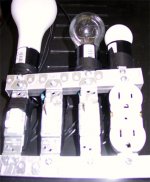
The experience of most people has been that if you blow one Q, all Qs (Q1, Q2, Q5) get blown. I have found that using a light bulb in series with primary gives you a good protection in that scenario (the current is limited by the bulb). I used the home-made contraption shown below to try various combination of different resistance bulbs. Finally, I figured that a 150W bulb gives you a best compromise between protection and a reasonable voltage (about 75V across primaries) for intial testing.
If you use 150W bulb (and R4 is max), the voltages should measure as shown in the picture at the bottom of this thread.
Also, use 1.5A fuse for the first power-up at full voltage and it will protect Qs in many situations. Infact I have been running my Zen4 with 1.5A sofar even in daily use.
I know patience is in limited supply after all the construction is complete (and I also blew up one set of Qs because of that), but a little diligence during the first power-up can save you a lot of time and effort.
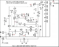
If we follow the signal's way
(I think I have found the right PDF)
Signal,
first it should go in R2, is that connected alright?
then C2, everthing okay?
Then R14//R15
Then C1//C4
to LOAD
If C2 is bad or not connected right
nothing will happen.
It is the only link between Q4, and the rest of AMP
I suppose you have set POT R4 for some 20 Volt at Drain of Q1
Yes, what I can see Source is at bottom for all transistors
except for Q4, the input transistor, which is P-channel
I should put a test-CD with 400 Hz signal to input.
Most AC-voltmeters can measure 400 Hz.
Some 0.3 Vrms will keep sgnal below 2.0 Vrms at output.
Then connect one probe to ground.
Then check all points in signals way
with AC-voltage meter. With the other probe.
Where does it disappear?
Re: Re: Zen4..only one channel working..
Forgot the picture:
jag said:
I used the home-made contraption shown below to try various combination of different resistance bulbs. Finally, I figured that a 150W bulb gives you a best compromise between protection and a reasonable voltage (about 75V across primaries) for intial testing.
Forgot the picture:
Attachments
Thanks for the help guys...
Jag: I should get new Q's and resistors tomorrow and will replace them as I think I blew Q1 when testing as I shorted it and R0/R1 blew and the fuse popped. I will replace and retest. (I lousy at de-desolderring I hope I do not ruin the board...any suggestions?) When you say you connect the bulb in series across the primaries, you are referring to the primaries of the transformers?
Halojoy: I have the pot set all the way counterclockwise. I believe I had 10V at the drain of Q1. I think I can use my stereophile test CD to perform the troubleshooting you described. Once Q's and resistors are replaced and not blowing again I'll follow that process. THANKS!
Here's a diagram of the value I measured prior to popping blowing things.
Thanks again,
Frank
Attachments
Yes, I compared your voltages.
And they seems to be alright, as far as I can see.
The 10 volts shouldn't stop amp from giving sound.
It only means that 75% of heat is on upper Q = 30 volt
and 25% heat on Q1
R0//R1 sets the current.
If they now are 0.47 and 1 ohm gives like 2 Ampere
Only using 1 ohm, will give only a third current (0.7 A)
One 2.2 ohm will give like 0.3 A
I shouldn't begin to change the supply voltage.
The circuit voltage is set by the zeners in the regulator, to about 40 volts.
Regulator then doesn't work if supply voltage go
below some 45 volt
update
I wanted to post an update after my long weekend of troubleshooting. I received the replacement parts on Saturday afternoon and successfully replace the Q's and R0 and R1. Fired it up and both channels worked but the right side was much softer compared to the left side. And the left side was really somewhat distorted. I also learned that I had some of the diodes backwards on the left side (Couldn't adjust R4 to get the proper voltage without shutting down the sound..my regulated voltage was only about 18v...what do you know, those diodes do have to go a certain direction ) so I swapped those as well. Not really knowing what to do next I started mapping out the voltages on both channels to see if there was a difference. I also used a 400hz test tone and tried to follow it through the circuit as Halojoy recommended. Everything matched except the AC signal was less on the right channel after passing R3. The AC signal only appeared on the lower portion of the circuit as you follow +/ground input through (via source of Q4/Q1). Is that how this works?? Anyway I could start another post with all the questions I have after reading up on mosfets and active current sources, so I won't digress here.....
Not knowing what to do next I decided to cut the output cables and try swapping cabling between the channels and viola! When I connected the speakers directly to the output cabling, bypassing the binding posts the amp opened up and sound was heard
I thought I had tried connecting the speakers directly to the pcb, but perhaps I did not make a good connection, and perhaps it was when I had a bad Q. Who knows, perhaps this was my only problem to begin with. I know one thing, I will never second guess a recommendation of a DIY elder (Halojoy) again..
I listened to the amp for about an hour in this configuration, adjusted R4 and it sounds great. It's not going to replace my Aleph5 (commercial version) but I'll compare the two in my main system when this ones done. Heatsinking seems to be working out ok.
Now I need to figure out how to make a proper connection with my binding posts. I have the cards copper posts with silver/rhodium plating. I had a heck of a time tring to solder them. Any recommendations, I'm apparently not making a good electrical conenction with them. Then to finish sanding/cleaning the face plate and cover.
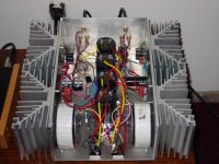
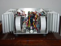
Here are a few pictures of it so far...
Thanks for you help Halojoy and Jag (I'm gonna build one of those light bulb contraptions for the next project!)
Frank
I wanted to post an update after my long weekend of troubleshooting. I received the replacement parts on Saturday afternoon and successfully replace the Q's and R0 and R1. Fired it up and both channels worked but the right side was much softer compared to the left side. And the left side was really somewhat distorted. I also learned that I had some of the diodes backwards on the left side (Couldn't adjust R4 to get the proper voltage without shutting down the sound..my regulated voltage was only about 18v...what do you know, those diodes do have to go a certain direction ) so I swapped those as well. Not really knowing what to do next I started mapping out the voltages on both channels to see if there was a difference. I also used a 400hz test tone and tried to follow it through the circuit as Halojoy recommended. Everything matched except the AC signal was less on the right channel after passing R3. The AC signal only appeared on the lower portion of the circuit as you follow +/ground input through (via source of Q4/Q1). Is that how this works??
Anyway I could start another post with all the questions I have after reading up on mosfets and active current sources, so I won't digress here.....Not knowing what to do next I decided to cut the output cables and try swapping cabling between the channels and viola! When I connected the speakers directly to the output cabling, bypassing the binding posts the amp opened up and sound was heard
I thought I had tried connecting the speakers directly to the pcb, but perhaps I did not make a good connection, and perhaps it was when I had a bad Q. Who knows, perhaps this was my only problem to begin with. I know one thing, I will never second guess a recommendation of a DIY elder (Halojoy) again..
I listened to the amp for about an hour in this configuration, adjusted R4 and it sounds great. It's not going to replace my Aleph5 (commercial version) but I'll compare the two in my main system when this ones done. Heatsinking seems to be working out ok.
Now I need to figure out how to make a proper connection with my binding posts. I have the cards copper posts with silver/rhodium plating. I had a heck of a time tring to solder them. Any recommendations, I'm apparently not making a good electrical conenction with them. Then to finish sanding/cleaning the face plate and cover.
Here are a few pictures of it so far...
Thanks for you help Halojoy and Jag (I'm gonna build one of those light bulb contraptions for the next project!)
Frank
Attachments
- Status
- This old topic is closed. If you want to reopen this topic, contact a moderator using the "Report Post" button.
- Home
- Amplifiers
- Pass Labs
- Zen4..only one channel working..