Hi elviukai,
this spreadsheet will help you I think from memory Version 3b calculates power incorrect, use Version 3A.
You really need to use duncans psu simulator to get some idea what your final rails will be under load, especially with 11 amps bias.
http://www.diyaudio.com/forums/showthread.php?postid=275481#post275481
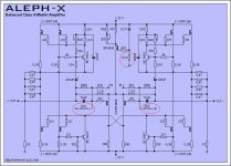
Hi Luke thanks for excel calculations. I already have 2 versions of them. unfortunately they do not tell whay they using one or other value of resistors wihich I marketed  I am not electronic engineer and woul be nice getting nice start point. I noticed that in higher power versions it lowers from 4.7kohm to 3.3kohm. what theese resistors doing?
I am not electronic engineer and woul be nice getting nice start point. I noticed that in higher power versions it lowers from 4.7kohm to 3.3kohm. what theese resistors doing? hi wufwaf. once somebody told me to rise input sensitivity to drive via passive praemp.( I using passive preamp and wanted better input sensitivity but not lowering input impedanse) increase 100kohm value. I increased to 130kohm. get arround 15V output at speakers and quickly changed my mind
ant theese 4.7-3.3ohm near input 9610 mosfets? why thery are varying. its pain when I do not know electronic basic knowlwdges
ant theese 4.7-3.3ohm near input 9610 mosfets? why thery are varying. its pain when I do not know electronic basic knowlwdges
thanks wuffwaff, and regarding theese 100 -33kohm resistors? thay also varying. and output resitors 4x 0.47ohm ,sometimes I noticed that in higher power verion people ad some pair = 6x 0.47ohm what does it means and decreasing output resitors do I need change output to ground resistors(33ohm) ?
Elviukai,
it´s the same story for the the output to ground resistors. Start with 100 Ohms and lower if absolute dc offset behaviour is not ok.
The source resistor value depends on the bias per fet you are using. Aim for 0,5-0,6V at the chosen bias.
The output resistors can vary too, lower values give less power dissipation and less voltage to steer the active current source. Tollerances will be bigger if the value get´s lower but normally you will set your ac-current gain with a pot first so that´s not such a problem.
William
start with 100ohm? all design I have ever seen use 33-22ohm(pfor example 3x100ohm)output to ground
tomorow is the big day -I will try to start up my aleph x monoblocks. 22v rails, 12.5A per channel, 16x irfp244, 1x 2Kw toroid per channel. I hope I will not blown anything as usualy
tomorow is the big day -I will try to start up my aleph x monoblocks. 22v rails, 12.5A per channel, 16x irfp244, 1x 2Kw toroid per channel. I hope I will not blown anything as usualy
evil  I quess nelson do not think this way because he would remove them somehow if you are telling that theese resistors must be qualitty ones? or no mater metal wirewound and caddock is the same evil? I looked carefully to aleph original comercial xa100 schematic and I think I see 6-8 resitors 0.47 or 1 ohm in paralel to ground.(total about 26 resitors- 10 source resitors for each fet and left is output and output to ground)
I think my babies will be more evil at low impedances than xa200
I quess nelson do not think this way because he would remove them somehow if you are telling that theese resistors must be qualitty ones? or no mater metal wirewound and caddock is the same evil? I looked carefully to aleph original comercial xa100 schematic and I think I see 6-8 resitors 0.47 or 1 ohm in paralel to ground.(total about 26 resitors- 10 source resitors for each fet and left is output and output to ground)I think my babies will be more evil at low impedances than xa200
where is Mc milan resistors? I have a bunch 400pieces vishay dale precision RS and CW resitors 10W 1% tolerance 1 and 2 ohms. I can paralel them as much as I need. 20x 10W woul be enought from output to ground. and also 20x 10w to output?
by the way nice to have some expalanations what pats what does in aleph x I found 4 excel files which calculates bias, heatsinks and output at selected impedance and ITS REALY helps a lot. I remeber my first alpeh 5 , I put black gate capacitor to feed LED diode now things are better but I still do not know basic theory. and I think most amateurs builders are feeling the same.
by the way nice to have some expalanations what pats what does in aleph x
I found 4 excel files which calculates bias, heatsinks and output at selected impedance and ITS REALY helps a lot. I remeber my first alpeh 5 , I put black gate capacitor to feed LED diode now things are better but I still do not know basic theory. and I think most amateurs builders are feeling the same.- Status
- This old topic is closed. If you want to reopen this topic, contact a moderator using the "Report Post" button.
- Home
- Amplifiers
- Pass Labs
- Aleph x resistors values