trango said:
. . . my ignorance . . .
I don't think so at all.
Your PSU must be all correct.
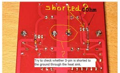
Nevertheless, before jumping over to the amp PCB, try to be sure of (the last one) that there is no short between the Darin-pin and the ground through the heat sink . . .
")
Regards
Attachments
I forgot this . . .
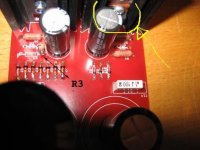
The picture is unclear for me, but it seems that there is no electrical insulation pad between the heat sink and the MOSFET (Drain body), while the heat sink is soldered to the grounding plate. If there is no insulation pad, the probability of electrical short between the Drain and the ground is high. I would like to suggest to insert an insulattion pad.
I hope this info will help.
And, wish your soonest successful trouble shooting . . .
Regards
Attachments
jh6you said:I forgot this . . .
The picture is unclear for me, but it seems that there is no electrical insulation pad between the heat sink and the MOSFET (Drain body), while the heat sink is soldered to the grounding plate. If there is no insulation pad, the probability of electrical short between the Drain and the ground is high. I would like to suggest to insert an insulattion pad.
I hope this info will help.
And, wish your soonest successful trouble shooting . . .
Regards
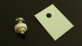
Actually, I provided insulating pads with the kits. The only thing required was a Nylon insert or Nylon screw.
Regards
Anthony
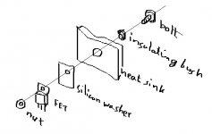
I have Kari's boards and the heat sink mounting pads are isolated from the ground plane, so no isolation of the pass FETs is required. Assembled, you might see a low resistance drain to ground due to the filter capacitors, but note that it is not a dead short and changes if you reverse the leads of your DMM.
I guess this rules out one possible cause of problems. Sorry that it doesn't fix it.
I guess this rules out one possible cause of problems. Sorry that it doesn't fix it.
Thanks for all input!
I appreciate your effort to help me, I've donated a small sum to the forum and I also hope that I soon will experienced enough to be able to help other DIYers with their problems (anyone needs help with some protein chemistry???).
Anyway, the excessive soldering of the positive rail heatsink seems to connect the FET to the groundplane. I've ordered replacement zeners and FETs and I hope that everything will be fine with the PSU when replace the zeners and isolate the FETs from the heatsink.
The FETs of the Boz card have been isolated so I don't think that is the problem in that case, but I have to check.
/Fredrik
trango said:Thanks for all input!
I appreciate your effort to help me, I've donated a small sum to the forum and I also hope that I soon will experienced enough to be able to help other DIYers with their problems (anyone needs help with some protein chemistry???).
Anyway, the excessive soldering of the positive rail heatsink seems to connect the FET to the groundplane. I've ordered replacement zeners and FETs and I hope that everything will be fine with the PSU when replace the zeners and isolate the FETs from the heatsink.
The FETs of the Boz card have been isolated so I don't think that is the problem in that case, but I have to check.
/Fredrik
Well while I am running Protien to Protien interactions and trying to express a specific series of Recombinat DNA on a PCR plate I have noted several errant markers. I can not determine if the issue is in the growth medium (FBS) or the Taq polymerase.
Just Kidding, I will get those parts out to you this week.
Anthony
I've got exacly the same phenomenon as Trango, plugged my Bosoz in yesterday, left channel was silent. 10,7V on the positive rail when the amp was connected, 63,4v unconnected. So I tried the left channel psu on the right channel, same result. Ok, something wrong with the psu, I can use one psu until I've fixed the broken one, I thought, so I connected the R-channel psu to both channels. Smoooooke. Now I've got no psu.......Some error on the left channel amp that breakes the psu, got to be drunk before I look into it.
Happy weekend everybody.
Happy weekend everybody.
plysch,
I'm sorry to hear that you also have problem with your Bosoz! I've fixed my PSU cards by changing the zeners and one of the IRF610s. Now both PSU measures nice (unloaded). I hope you can fix the PSUs in the same way?
I 've started to look into the amp cards. The broken card has an short-circut between 0 and +60. I don't know how to localize the which component that cause this short circut. As far as I can say all soldering work is OK.
I would really appreciate some suggestions -where and how to start?
/Fredrik
The "short" could be the 1000 uf capacitor from +60 to ground. Does it stay a dead short if you keep the leads there? How about if you reverse the leads?
The first thing I'd check after looking for solder bridges is the FETs. They should measure quite high resistance between Source and Drain. Gate to Source resistance should also approach open circuit. Are teh LM4040s inserted correctly?
Do you have access to a variac/autotransformer to bring the rails up slowly? If not, use a 100R 1/4W resistor in series with each rail between BOSOZ and PSU. It won't last long, even if the BOSOZ is working right, but it will limit the current in case of a dead short.
What is the voltage across the 100R on the positive rail? Does it match the negative? If not you have a short to ground somewhere. Pull the 1000 uF caps and try again. If the current is now the same on both rails you've found your culprit.
If the 100R take a minute or so to blow (not nearly instantaneously) you can replace them with 10R or 100R 1W and measure the operating point.
What is the voltage on the sources of the differential pair (the ones connected together, closest to the lone CCS FET)? It should be around -4V.
What are the voltages at the Sources of the cascode FETS?
That ought to get you started. Post your results and lets see where you are.
Trango.
That sounds as a good start, I haven't fixed my PSU's yet, I've ordered some parts, zeners & FET's.
I have no short circut on my broken board, the resistance to ground on both positive rail & neg. rail are infinite.
On the working board I have infinite res. between +rail to ground and 250k between -rail to ground. I'm a bit confused, got to study the shematics for a while......
BobEllis,
Thank's for your advice - really appreciate your help!
First I tested the "non shorted" amp card and connected it to the PSU. No smoke and stable voltage over the rails of the PSU. Without further testing I assume that this amp card is OK. My plan is to use this card as an "positive" control when I try to localise the problem in the shorted amp card.
Then I've turned my attention to the broken card.
The LM4040 is inserted correctly and the soldering work seems OK with no bridges as far as I can tell.
I've mesured the resistance over the FETs and its > 50 kOhm over all pinns. I've measured the resistance over the LM4040 and I've no short in this region. At this point I tried to connect the Amp card to PSU using your 100R trick. "Intrestingly" there where smoke coming, most likely from the Ref2 LM4040, before I quickly broke the current.
First question, is it likely that the reference is damaged and if so, how can I detect this? Or is it better just to by a new reference?
I measured the resistance of the 1000 caps, still soldered on the card, the polarity is OK. C2 47 Ohm, C3 0.5 Ohm. I suppose this is a bad sign?
Now I'm a bit confused, you have to excuse my poor knowledge about "electronic english". When you refer to the leads do you mean the "connector thing that you solder to the card" which, my caps, by the way, have three of? If so, what shold I do to reverse the leads, exchange the polariy or connect currently "unused" third lead to the positive pole? I feel rather ignorant when I ask these questions
Thats how far I've managed to measure this evening.
/Fredrik
Thank's for your advice - really appreciate your help!
First I tested the "non shorted" amp card and connected it to the PSU. No smoke and stable voltage over the rails of the PSU. Without further testing I assume that this amp card is OK. My plan is to use this card as an "positive" control when I try to localise the problem in the shorted amp card.
Then I've turned my attention to the broken card.
The LM4040 is inserted correctly and the soldering work seems OK with no bridges as far as I can tell.
I've mesured the resistance over the FETs and its > 50 kOhm over all pinns. I've measured the resistance over the LM4040 and I've no short in this region. At this point I tried to connect the Amp card to PSU using your 100R trick. "Intrestingly" there where smoke coming, most likely from the Ref2 LM4040, before I quickly broke the current.
First question, is it likely that the reference is damaged and if so, how can I detect this? Or is it better just to by a new reference?
I measured the resistance of the 1000 caps, still soldered on the card, the polarity is OK. C2 47 Ohm, C3 0.5 Ohm. I suppose this is a bad sign?
The "short" could be the 1000 uf capacitor from +60 to ground. Does it stay a dead short if you keep the leads there? How about if you reverse the leads?
Now I'm a bit confused, you have to excuse my poor knowledge about "electronic english". When you refer to the leads do you mean the "connector thing that you solder to the card" which, my caps, by the way, have three of? If so, what shold I do to reverse the leads, exchange the polariy or connect currently "unused" third lead to the positive pole? I feel rather ignorant when I ask these questions
Thats how far I've managed to measure this evening.
/Fredrik
Sorry, that should read "reverse the multimeter leads."
You can test the voltage reference the same way that you do a zener. It should look like a regular diode one way, and a high resistance the other. If a dead short, replace it.
Place a resistance suitable to give ~5mA current in series with your reference. Say you want to test with your 60V supply, you could use a 10K (1/2W or greater) in series to drop the 50V left after the reference drops 10V. Something like 2K on the low voltage side would work, too, just watch polarity. If you don't get 10V, then the reference is bad.
You can use a 9.1V zener (vertically) in place of the LM4040 if you have spares and want to test before the LM4040s arrive.
C3 looks like a goner if that is measured out of the circuit. C2 maybe as well, if it isn't rising.
BobEllis, this would be very difficult without your help!
Still, I'm starting to feel very frustated! I have remove the C2 and C3 1000 uF caps. When I measure the resistance of these after the removal they both have rather high resistance. If I measure from the now empty solder pads I have a short at the C3 position. I guess that means that the caps were OK the hole time and the short have som other origin. However, I've been trying to read the schematics and I cannot se how to short C3 at the PCB.
I've also found another short, between the GND and -IN, I suppose they are related in some way?
Any suggestions?
plysch, I hope you are doing better than me, any progress?
/Fredrik
The - terminals of both C2 and C3 SHOULD be grounded. If your positive terminals are shorted to ground that is a problem.
The -In should be well above ground - there should be a 10K resistor between it and the rest of the circuit and 100K from there to ground. Check the values of the whole stack of resistors on the C3 side of the board. Maybe you burned through the soldermask and connected something to the ground plane.
If the Fets are bad they are likely shorted which could show as a short from the + terminal of C3 to the gate of Q4 to your short to ground. Look at the Q's as circuit junctions and imagine the connections then.
- Status
- This old topic is closed. If you want to reopen this topic, contact a moderator using the "Report Post" button.
- Home
- Amplifiers
- Pass Labs
- Xbosoz HELP (Karis PCB)