I love D1 stage . And implementet at least with 4 dacs . Will need to modify the biasing network a bit if the dc point of the dac is different from 0 volt . An example is the Philips tda 1545 wich requires 3.3 volts as dc working point.
Currently I am using the lovoltech j fet in that circuit . I am very happy .
Currently I am using the lovoltech j fet in that circuit . I am very happy .
Stefano,
I´m currently building my D1 stage with different options.
I´m still no really lucky. my CDP (shanling CD-S100MK2) has a PCM1738 inside. This chip seems to work best into a "virtual" ground, the common Voltage is set to 2,50V.
See this picture, and thread: http://www.diyaudio.com/forums/attachment.php?s=&postid=365903&stamp=1081271528
http://www.diyaudio.com/forums/showthread.php?s=&threadid=31732&highlight=PCM1738
I tried already a few different adjustments and I thought it were good, but after long listening I´m sure, I´m missing dynamic.
Would you please posting your lovoltech D1? I´m working at a 2SK389 based D1, very different to original. I thought too about LU1014d, but those needs a lot of current to operate in "triode region"
Best Regards
Adam
No, really also in a single ended set up I like dynamics , very correct . But compressions and dynamics depends on power supplies implementation and a number of other things.
With j fet (lovoltech)there is a step forward by my point of view ,and often I can see the mixing consolle very clearly . It is a nice sensation .
I wasnt so happy with 2sk s .
Absolutely the lovoltech require matching between channels . The difference is quite audible and not at all subtle.
I started by inserting jfets in the same circuit , just adjusting the bias ... and all seems to work pretty well .
stefanobilliani said:No, really also in a single ended set up I like dynamics , very correct . But compressions and dynamics depends on power supplies implementation and a number of other things.
With j fet (lovoltech)there is a step forward by my point of view ,and often I can see the mixing consolle very clearly . It is a nice sensation .
I wasnt so happy with 2sk s .
Absolutely the lovoltech require matching between channels . The difference is quite audible and not at all subtle.
I started by inserting jfets in the same circuit , just adjusting the bias ... and all seems to work pretty well .
Thanks Stefano for your insights.
Could I ask, what DAC are you using?
-David
hehehe I have the Philips tda15145 but every part of the circuitry has separated supplies , laser motors drivers and clock included .
I can assure you that it works very very good .
I had also nice performances with sony current pulse , in that case in a balanced configuration .
The philips is 16 bit converter , sony is tipically 1 bit.
I can assure you that it works very very good .
I had also nice performances with sony current pulse , in that case in a balanced configuration .
The philips is 16 bit converter , sony is tipically 1 bit.
stefanobilliani said:I love D1 stage . And implementet at least with 4 dacs . Will need to modify the biasing network a bit if the dc point of the dac is different from 0 volt . An example is the Philips tda 1545 wich requires 3.3 volts as dc working point.
Currently I am using the lovoltech j fet in that circuit . I am very happy .
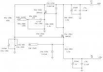
Assuming that I have 0 volt out from the DAC, what do I have to change to the circuit to use Lovoltech Jfet instead of IRF610. My thinking is that I need to change the two 1.5K resistors to a different value to bias the Jfet? The schematic that I am looking at is attached.
Attachments
agent.5 said:
Assuming that I have 0 volt out from the DAC, what do I have to change to the circuit to use Lovoltech Jfet instead of IRF610. My thinking is that I need to change the two 1.5K resistors to a different value to bias the Jfet? The schematic that I am looking at is attached.
JFET Vgs is negative, unlike MOSFET, so instead of tying r5a to +30 tie it to -30. The 1.5K resistors control gain, not bias, to change current bias change the 3.3K resistor.

Here's Stefano's Jfet implementaton of the D1:
http://www.diyaudio.com/forums/showthread.php?postid=616248#post616248
-David
http://www.diyaudio.com/forums/showthread.php?postid=616248#post616248
-David
dw8083 said:Here's Stefano's Jfet implementaton of the D1:
http://www.diyaudio.com/forums/showthread.php?postid=616248#post616248
-David
Thanks for the link. I may be totally wrong here as my sand knowledge is horrible. I think Stefano implementation is different than Promitheus's circuit (the gif that I attached). In P's circuit, T1b has a 1.5K resistors on the drain (top) and an identical 1.5K resistor is placed on the source (bottom) of T2b. The output of the entire circuit is taken off the source of the second(following) Mosfet. This reminds me of the Aikido stuffs over at the tube section.
http://www.tubecad.com/articles_2001/Inv_Dist_Cancellation/CompInvDisAmp.pdf
dw8083 said:Here's Stefano's Jfet implementaton of the D1:
http://www.diyaudio.com/forums/showthread.php?postid=616248#post616248
-David
This is a D1 stage without the follower. For another JFET based D1 with follower and CCS see here
relder said:
JFET Vgs is negative, unlike MOSFET, so instead of tying r5a to +30 tie it to -30. The 1.5K resistors control gain, not bias, to change current bias change the 3.3K resistor.
Thats correct .
Values depend on devices selection , anyway inserting the lovoltechs in the original circuit - I have slightly lower rails- will find out they are working at Vgs about -2.1 volt , and Vds around 8 volt .
Having DAC dc point as high about 2.5 - 3,5 volt the gate of the cascode jfet will be at a positive voltage .
If the DAC works at 0volt the Jfet gate will be at -2.1 volt or so .
I am tempted to raise the gain a bit , using R6 at 1.8k or 2.2k .. will see .
In that case will be necessary to change the bias (R2) in order to let the buffer have a nice working point also .
I am building D1 output stage and I use NP mosfet series regulator at +/-30V and IRF510. Questions:
1. When power on, dac input voltage will drift from 0.6v to +/-0.005V (limit for my offset adjuetment). When power off, the dc offset will drift up to 2.5Vdc. The question is will this dc drift damage the DAC output pin?
2. I find that most diyer use LM317 or 7815 IC regulator. Is it a must to improve the input dc offset tolerance due to temperature drift?
Spencer Cheung
DAC D1 for sony ES20
Hi,
Have You any diagram schematic D1 DAC for sony ES? I've sony cdp-xa 20es and want try this DAC with that CD player.
If You have electric circuit please send me: jc78@interia.pl
Thanks a lot,
Jacek
hehehe I have the Philips tda15145 but every part of the circuitry has separated supplies , laser motors drivers and clock included .
I can assure you that it works very very good .
I had also nice performances with sony current pulse , in that case in a balanced configuration .
The philips is 16 bit converter , sony is tipically 1 bit.
Hi,
Have You any diagram schematic D1 DAC for sony ES? I've sony cdp-xa 20es and want try this DAC with that CD player.
If You have electric circuit please send me: jc78@interia.pl
Thanks a lot,
Jacek
2 x PCM1794 + D1
I adjusted the original D1 output stage to two PCM1794 in mono-mode. You have to get 2.4V at IN and a quiescent current of about 17mA.
The 100k between pot and "+" replace by 68k to get the offset. For the current instead of 3k3 to "-" use 2k, instead of 1k5 to "+" use 820R. Actually I have 1938R and 857R by adding parallel resistors (4k7, 2k), which is better because they have to burn a little over 1/2 W.
The thing is now too loud for my bosoz so I have to reduce the output like the original volume control. Or maybe I should drive the Aleph-x directly ...
- Status
- This old topic is closed. If you want to reopen this topic, contact a moderator using the "Report Post" button.
- Home
- Amplifiers
- Pass Labs
- Anyone built a Pass D1 I/V for a TI1794 or TI1794 DAC?