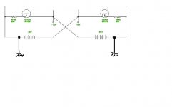
Well, there was a question some posts ago and recently regarding why we need those 2 Rs to Gnd... The 2 power supplies that supply the output circuit are floating. They have no Gnd connection. Most discussions of drivers, refrences some drive voltage to ground. Drive voltage refrenced to Gnd will do nothing to the output. The drive needs to be Gate to source. Hence, the Rs allow a gate to source voltage return path while still alowing the output supplies to float.
My circuit has no feedback and it will not work without the Rs. Transformers were the original method to drive this thing. They supply an isolated gate to source drive.
And then ther is me. I'm the one who wants to use some parameters that are most important to make the Rs in my circuit optimum. I've just been putting it off for bench evaluation. I beleive they will be most important on a real circuit with imbalances and offsets, etc. All the perfection of the simulator is not pointing out anything particular to help me understand??? I have simulated small value Rs in 1 source to see what happens. The offsets at the output will be lower with the lower value Rs...
Did I help anyone understand Circlotron, and of coarse New-Tron any better??? Yes it's weird. I don't even think it's one of those agreed upon Class A or AB types of classes...
flg said:
The offsets at the output will be lower with the lower value Rs...
I once again looked into Patrick's . . .
If there are those resistors, I think that the values closer to the speaker impedance would better help to reduce the DC offset . . . but . . .
JH
I don't think that will work jh6you. You need a Drain load don't you. You have a battery??? If I see that right? you are trying to get a common source configuration to work? I have not tried that yet... There are also some inductor loaded follower designs that have gain???
A few thoughts:
Kirchoff's Law dictates that the circuit will not work unless there
is some DC attachment from the input circuit to the output
circuit to allow a difference in drive current to the output devices.
The 2 resistors across the load provide an arbitrary virtual
ground for this, and we see that the currents coming from the
Drains of the input devices as well as feedback currents must
flow through these resistors on their return path to the
input stage. As such, they should be as low a value as
practical, but not so low that they load down the output
undesirably. My own thinking is that 22 ohms would probably
be that lowest practical value.
The performance of this technique will then hinge on the power
supply rejection and common mode rejection of the input stage,
so that cascoding and a high quality CCS will be important.
As to AB performance of this a circuit - forget it. There is not
enough feedback to give low distortion at the crossover point.
Nelson,
Many thanks for the analysis.
> As to AB performance of this a circuit - forget it. There is not
enough feedback to give low distortion at the crossover point.
Meaning pure Class A ?
(Just want to make sure I understand correctly language wise, by no means questioning the statement.)
Would you use a self biasing cascode (like e.g. J174 with high Idss which would give about 5V Vds across the diff pair), or at fixed voltage (e.g. ZVP3310A with gate at -7V wrt. Gnd ? What are the pros & cons ?
Patrick
May I ask for one more hint ?
Suppose I only want 10-15W Class A (just to drive tweekers), and I want to use Loveltech Power JFETs with Cascode as output, like Grey is proposing. I guess I would be biasing single JFET at 1.3A (2 Power JFETs per channel). Would I still be able to use the triode parts of the curves ? I have no Power JFETs on hand yet, and there is insufficient information on the datasheet. What would be the best cascode voltage ?
Many thanks in advance,
Patrick
Nelson Pass said:
Kirchoff's Law dictates that the circuit will not work unless there
is some DC attachment from the input circuit to the output
circuit to allow a difference in drive current to the output devices.
Aha . . . Kirchoff's rule . . .
The basic is almost same as shear flow analysis with multicells we are working on it daily.
By the way, I was always confused if the simultaneous linear equaions are more than two. Never improved yet . . .

Regards
JH
EUVL said:Any chance of publishing some measurements (Id vs Vds for various fixed Vgs) around that region ?
You are in the region where it varies quite a bit. If you check
ZV9, you'll get some incomplete information.
> You are in the region where it varies quite a bit. If you check ZV9, you'll get some incomplete information.
Had done so already before asking. Guess I just have to wait until the JFETs arrive, whenever that might be.
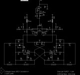
In the meantime, this is the first attempt for the power JFET version. Of course you are right, the MOSFET version published earlier here has very little gain. This should have about 30dB at 4 ohms, and is, at least according to quick hand calculations, stable to over 1MHz.
The over-current protection is probably not quite sufficient, but I have not figured out an elegant way of doing that yet.
Should I expect expect quite a bit of thermal drift for the Power JFETs, bearing in mind their very high transconductance ?
Patrick
Had done so already before asking. Guess I just have to wait until the JFETs arrive, whenever that might be.
In the meantime, this is the first attempt for the power JFET version. Of course you are right, the MOSFET version published earlier here has very little gain. This should have about 30dB at 4 ohms, and is, at least according to quick hand calculations, stable to over 1MHz.
The over-current protection is probably not quite sufficient, but I have not figured out an elegant way of doing that yet.
Should I expect expect quite a bit of thermal drift for the Power JFETs, bearing in mind their very high transconductance ?
Patrick
Attachments
Firstly my apologies for posting the wrong schematics. It was of course not the one with Power JFET, but the previous MOSFET circuit.
It had taken some time and I still could not make the file small enough for posting, so we'll have to do it in two halves.
This is the overall view.
Patrick
It had taken some time and I still could not make the file small enough for posting, so we'll have to do it in two halves.
This is the overall view.
Patrick
Attachments
- Status
- This old topic is closed. If you want to reopen this topic, contact a moderator using the "Report Post" button.
- Home
- Amplifiers
- Pass Labs
- The New-Tron